Amosphere NPM Installation Procedures (WCS) Release 1.
Copyright 2002 SOMA Networks, Inc. All Rights Reserved. SOMA Networks, Inc. 185 Berry Street Suite 2000 San Francisco, CA 94107 U.S.A. Phone +1.415.882.6500 Fax +1.415.882.6501 SOMA, SOMA Networks and the star-and-circle logo are trademarks of SOMA Networks, Inc. All of SOMA Networks’ product names are trademarks of SOMA Networks, Inc. All other company and product names may be trademarks or registered trademarks of their respective owners. Products and services of SOMA Networks, Inc.
Chapter 0 PREFACE This book explains how to install a Network Port Manager (NPM) basestation. NPM installation includes installing the NPM racks, connecting the NPM to the network core, and powering on the system. This book is intended for field technicians with experience installing and configuring telecommunications equipment at cellular basestations and network operations centers. How This Book Is Organized Table 1 shows how information in this book is organized.
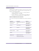
Amosphere NPM Installation Procedures (WCS) Related Documentation SOMA Networks documentation is modular, so users need to read or carry only those components relevant to a particular job function. This guide makes crossreferences to the following documents: Amosphere NPM Maintenance Procedures – provides procedures for performing maintenance on the NPM. Amosphere OAMP Guide – provides installation and configuration instructions for the initial commissioning of an NPM basestation.
Third-Party Documentation Table 3 shows third-party documents that provide additional information which may be useful when installing the NPM. Document Description Central Office Environment Installation/Removal Generic Requirements (GR-1275-CORE) Available from Telcordia Technologies, Inc. Provides generic installation requirements for telecommunication suppliers and carriers. Zyfer AccuSync-R GPS Synchronized Time and Frequency Instrument User’s Manual (377-8006) Available from Zyfer, Inc.
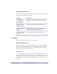
Amosphere NPM Installation Procedures (WCS) Unless otherwise specified, SI prefixes with bits and bytes in this document refer to a factor of 10. Typographical Conventions Table 4 shows how different fonts are used throughout this guide. Font Usage Example Courier System output and all things involving source code (commands, samples, methods, functions, objects, variables, types, constants, fields, properties, and structures) echo “NETWORKING=yes HOSTNAME=soma GATEWAY=10.110.0.
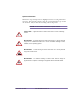
Special Information Information of special importance is highlighted in the text using indentation and icons. The following examples show the special information types used in the document. They are listed in ascending order of importance. N O T E : A note contains information of special interest. C A U T I O N : A general caution is shown when there is a risk of affecting ! service.
Amosphere NPM Installation Procedures (WCS) Trademark Identification The following SOMA Networks trademarks are used without notation in the rest of this document: AmosTM AmosphereTM SOMApageTM SOMAportTM Tell Us How We Are Doing If you have any feedback about this document, e-mail Technical Communications at SOMA Networks: docs@somanetworks.com.
CONTENTS Chapter 1 Installation Overview ............................................................................ 17 Installation Process Summary . . . . . . . . . . . . . . . . . . . . . . . . . . . . . . . . . . . . . . . . 18 Necessary Conditions for Installation . . . . . . . . . . . . . . . . . . . . . . . . . . . . . . . . . . 19 Chapter 2 Site Preparation..................................................................................... 21 Physical Requirements . . . . . . . . . . . . . . .
Amosphere NPM Installation Procedures (WCS) Attach the Main and Return Power Cables . . . . . . . . . . . . . . . . . . . . . . . . . . . . . 65 Test Power Supply Voltage and Ground . . . . . . . . . . . . . . . . . . . . . . . . . . . . . . . 67 Attaching the Shelves and Modules .................................................................... Radio Rack Layout . . . . . . . . . . . . . . . . . . . . . . . . . . . . . . . . . . . . . . . . . . . . . . . RF Rack Layout . . . . . . . . . . . . . . . . .
Contents Index .............................................................................................................................
Amosphere NPM Installation Procedures (WCS) 12 Part 003609A revision 01 December 16, 2002
L IST OF TABLES Chapter 0 Chapter 1 Installation Overview Table 1.1 Installation Process Summary . . . . . . . . . . . . . . . . . . . . . . . . . . . . . . . . 18 Chapter 2 Site Preparation Table 2.1 Table 2.2 Table 2.3 Table 2.4 Table 2.5 Table 2.6 Table 2.7 Table 2.8 Table 2.9 Table 2.10 Table 2.11 Table 2.12 Table 2.13 Table 2.14 Table 2.15 Rack Dimensions. . . . . . . . . . . . . . . . . . . . . . . . . . . . . . . . . . . . . . . . . . Weight of NPM Components . . . . . . . . . . . . . . . .
Amosphere NPM Installation Procedures (WCS) Table 4.3 Table 4.4 Table 4.5 Table 4.6 Table 4.7 Table 4.8 Table 4.9 Table 4.10 Table 4.11 Table 4.12 Table 4.13 Table 4.14 Table 4.15 Table 4.16 Table 4.17 Table 4.18 14 Attaching the Shelves and Modules Procedure Summary . . . . . . . . . . 71 Populating the Shelves Procedure Summary . . . . . . . . . . . . . . . . . . . . 81 Utility Shelf Layout (Front-Facing Cards) . . . . . . . . . . . . . . . . . . . . . . 82 Utility Shelf Layout (Rear-Facing Cards) . . .
LIST OF F IGURES Chapter 0 Chapter 1 Installation Overview Chapter 2 Site Preparation Figure 2.1 Figure 2.2 NPM Dimensions . . . . . . . . . . . . . . . . . . . . . . . . . . . . . . . . . . . . . 22 Sample Amosphere Network . . . . . . . . . . . . . . . . . . . . . . . . . . . . . . 32 Chapter 3 Pre-Installation Activities Figure 3.1 Figure 3.2 Figure 3.3 Figure 3.4 Wrist-Strap Grounding Point . . . . . . . . . . . . . . . . . . . . . . . . . . . . . Ethernet Switch Jumper Configuration . . . .
Amosphere NPM Installation Procedures (WCS) Figure 4.20 GPS Antenna Assembly . . . . . . . . . . . . . . . . . . . . . . . . . . . . . . . . .110 Figure 4.21 RFSS with TMA Antenna Configuration . . . . . . . . . . . . . . . . . . . .112 Chapter 5 16 Power-On Procedures Chapter 6 On-Site Software Installation and Configuration Procedures Figure 6.1 Figure 6.2 GPS Serial Interface Adapter . . . . . . . . . . . . . . . . . . . . . . . . . . . . .120 Ethernet Switch Serial Cable . . . . . . . . . . . . .
Chapter 1 INSTALLATION OVERVIEW Chapter 1 This chapter provides an overview of the installation process. Please familiarize yourself with the installation process in general before proceeding to the next chapter. Contents Installation Process Summary ................................................................................. 18 Necessary Conditions for Installation .......................................................................
Amosphere NPM Installation Procedures (WCS) Installation Process Summary Installation of an NPM basestation should take approximately two to three days, assuming the site already meets the requirements specified in Chapter 2, “Site Preparation”. Three people should be present during the installation, especially when moving NPM equipment. Table 1.1 lists the procedures to install an NPM.
Chapter 1: Installation Overview Necessary Conditions for Installation The installation procedures in this manual assume that the following conditions have been met: The core servers located at the network operations center (NOC) are operational and connected to the backhaul. The backhaul has been tested and is connected to the edge routers. The utility bus controllers, radio sector controllers, and application hosts are each configured in their BIOS to boot from the correct source.
Amosphere NPM Installation Procedures (WCS) 20 Part 003609A revision 01 December 16, 2002
Chapter 2 SITE PREPARATION Chapter 2 This chapter identifies the requirements that your site needs to meet before you can proceed with the installation of the NPM. Please review these requirements before proceeding to the next chapter. Contents Physical Requirements ............................................................................................ Environmental Requirements ................................................................................... Electrical Requirements ..............
Amosphere NPM Installation Procedures (WCS) Physical Requirements Before you begin installing the NPM, read the following physical requirements. Ensure that each requirement is met before proceeding with the installation, and consult your methods of procedures (MOPs) for information concerning transportation method, route, and precise installation location.
Chapter 2: Site Preparation Weight The total weight of a 6-sector NPM is approximately 491 kg (1099 pounds). The NPM has a floor loading of approximately 319 kg/m2 (66 pounds/foot2), as per Telcordia Technologies GR-1275-CORE. A dolly or crane is required to move the racks. Table 2.2 shows the weight of the different NPM components. Component Weight Empty single rack 69.2 kg (155 pounds) RF rack, filled to capacity 276.2 kg (609 pounds) Radio rack, filled to capacity 204.
Amosphere NPM Installation Procedures (WCS) Torque Values Table 2.3 shows the recommended torque values for the different sizes of fasteners used in the NPM racks. Fastener Size Recommended Torque #4 (0.112-inch) screw 6 inch-pounds #6 (0.138-inch) screw 12 inch-pounds #8 (0.
Chapter 2: Site Preparation Environmental Requirements Before you begin installing the NPM, read the following environmental requirements. Ensure that each requirement is met before proceeding with the installation and consult your MOPs for procedures concerning building requirements, hazardous materials and waste, and environmental systems.
Amosphere NPM Installation Procedures (WCS) Altitude Certain components in the NPM are sensitive to altitude. Table 2.6 shows the altitude requirements for the NPM. Operational State Altitude Requirement Operating –60 m to +1800 m (–197 feet to +5904 feet) Table 2.6 Altitude Requirements Airflow Each NPM rack requires 0.6 m (2 feet) of open space in front of and behind it to allow suitable airflow for cooling. Each cooling fan draws approximately 600 cubic feet per minute (CFM) of air.
Chapter 2: Site Preparation Electrical Requirements Before you begin installing the NPM, read the following requirements. Ensure that each requirement is met before proceeding with the installation and consult your MOPs for procedures concerning power, grounding, and high-risk cut-over activities. W A R N I N G : Failure to meet the following requirements may result in personal injury and cause damage to or destruction of the NPM basestation and surrounding equipment.
Amosphere NPM Installation Procedures (WCS) Main Power Bay Circuit Breaker Size Each NPM rack requires three +24V DC inputs. Table 2.9 shows the recommended circuit breaker sizes for each +24V line. Configuration Radio Rack RF Rack 6 sectors 40A per breaker (3) 130A per breaker (3) 3 sectors 30A per breaker (3) 70A per breaker (3) 1 sectors 20A per breaker (3) 40A per breaker (3) Table 2.
Chapter 2: Site Preparation NPM Circuit Breaker Current Loads Each NPM rack contains a power distribution panel (PDP). The PDP has up to 16 circuit breakers (CBs). Each breaker switch controls the power to a specific NPM component. Individual NPM components can be powered off by setting the appropriate breaker switch to the OFF (down) position. Table 2.11 shows the maximum current loading of the circuit breakers in the RFSS and radio rack PDPs.
Amosphere NPM Installation Procedures (WCS) Fuses PDP The PDP in each NPM rack contains three 0.25A, 250V, fast-blowing fuses (1.25 × 0.25 inch) to protect the alarm cards on the utility shelf from damage in the event of an electrical overload. WARNING: Circuit breakers protect the other shelves, cards, and modules in the NPM. Removing the fuses does not disable power to the circuit breakers, PDP, shelves, or modules. Table 2.12 shows the +24V DC feed to which each fuse is connected.
Chapter 2: Site Preparation Rack Grounds Table 2.13 shows the grounding requirements for each rack. Ground Type Requirement Frame ground Each NPM rack requires one connection to its frame assembly for use as a frame ground. The frame ground cable uses #6 AWG wire. Main ground Each NPM rack requires one connection to the main building ground, such as the master ground bar (MGB). The ground cable uses #6 AWG wire.
Amosphere NPM Installation Procedures (WCS) Network Requirements Before you begin installing the NPM, read the following network requirements. Ensure that each requirement is met before proceeding with the installation and consult your MOPs and E1 package for procedures involving the network equipment. Figure 2.2 shows an example of an Amosphere network with redundant systems.
Chapter 2: Site Preparation PSTN Gateway The NPM does not connect directly to the PSTN. A PSTN gateway, such as a PRI, connects the Amosphere IP-based equipment to the circuit-switched PSTN. N O T E : Ensure that any equipment connecting the NPM to the PSTN is UL-listed. Edge Routers The NPM requires a connection to at least one edge router configured to direct packets between the NPM and the network core. The edge router connects to the NPM using 100-Mbit/s Ethernet.
Amosphere NPM Installation Procedures (WCS) Site Requirements Each site has unique requirements and characteristics. See your E1 package for specific requirements relating to your installation. The E1 package contains the site’s floor plan, cabling routing and termination, and other site-specific Restricted Access Access to the site must be controlled by the authority for that location and granted through the use of special tools, locks and keys, or other means of security.
Chapter 2: Site Preparation Antenna Mounting Locations The NPM uses two antennas (main and diversity) per sector. Ensure that your tower can support the number of antennas shown in Table 2.15. Sectors Supported by NPM Required Antennas 1 2 2 4 3 6 4 8 5 10 6 12 Table 2.15 NPM Antenna Requirements N O T E : See the specifications of your antennas for information about size and weight requirements.
Amosphere NPM Installation Procedures (WCS) Isolated Ground Plane Environment Ensure that the NPM will be installed in an isolated ground plane environment as defined in Telcordia Technologies GR-1275-CORE. Master Ground Bar Requirements The site’s master ground bar (MGB) must be connected to the building principal ground’s electrode system.
Chapter 2: Site Preparation Ground Resistance The resistance of the building principal ground should be as low as practically possible (typically less than 5Ω). Under no circumstances should the resistance exceed the local electrical utility limits of 25Ω (NEC article 250-56, 1999). Additional Site Requirements See Telcordia Technologies GR-1275-CORE for a comprehensive description of generic site requirements.
Amosphere NPM Installation Procedures (WCS) 38 Part 003609A revision 01 December 16, 2002
Chapter 3 PRE-I NSTALLATION ACTIVITIES Chapter 3 This chapter lists the tools and equipment required for installing and testing the NPM equipment. It also provides procedures for unpacking the NPM and configuring individual cards and shelves. Contents Preparing for Installation .......................................................................................... 40 Configuring Cards and Shelves ...............................................................................
Amosphere NPM Installation Procedures (WCS) PREPARING FOR INSTALLATION This section describes precautions, equipment, and tasks that should be reviewed or performed prior to beginning the NPM installation. Table 3.1 shows the topics described in this section. Topics Page Antistatic Precautions 41 Equipment, Tools, and Supplies Checklists 42 Unpack the Equipment 44 Review Inventory Checklist 45 Table 3.
Chapter 3: Pre-Installation Activities Antistatic Precautions W A R N I N G : Components in the NPM are highly sensitive to electrostatic discharges (ESD). Follow the procedures described below to prevent unseen damage from occurring. To prevent damage to NPM components from static electricity: Do not handle circuit boards unless you are using the appropriate antistatic protection, such as wrist straps, boot straps, boots, or a conductive mat.
Amosphere NPM Installation Procedures (WCS) Equipment, Tools, and Supplies Checklists Tools The following tools are recommended for a typical NPM installation: Allen key set Platform stepladder (6-foot) Bolt cutter Plumb bob Cable ties Portable bandsaw kit Chalk line Scissors Drill bits (metal and masonry) Scratch awl Electrical tape Shims (for leveling NPM) Extension cord Socket sets (Imperial and metric) Flat file Strap (with buckle) Framing square Tap
Chapter 3: Pre-Installation Activities Safety Equipment The following safety equipment is recommended for a typical NPM installation. Ear plugs Flashlight Electrical gloves Portable eye-wash station ESD straps Safety glasses First aid kit Safety shoes Test Equipment Table 3.2 shows the equipment recommended for testing NPM functionality.
Amosphere NPM Installation Procedures (WCS) Unpack the Equipment The NPM racks are delivered on shipping pallets. Each rack is secured in an upright position and is bolted to the pallet. Additional equipment is delivered in separate shipping boxes. To unpack the NPM equipment 1 Transport the shipping boxes to the installation area using a dolly or pallet jack. 2 Inspect the exterior packaging for any noticeable damage that may have occurred during shipment.
Chapter 3: Pre-Installation Activities Review Inventory Checklist Table 3.3 shows the paperwork that ships with each NPM. Document Description Anchor kit Lists installation kit contents NPM BOM Lists every component in the NPM Chassis inspection checklist Factory inspection of each utility and radio shelf Table 3.3 NPM Inventory Documents To check the NPM inventory 1 Perform an inventory check using the checklists provided with the E1 package and BOMs.
Amosphere NPM Installation Procedures (WCS) CONFIGURING CARDS AND SHELVES Some of the jumpers and switches on the cards and shelves in the NPM require configurations which differ from the factory defaults. This section provides the procedures for making the necessary alterations. Table 3.4 shows the actions described in this section. Action Page Configure Ethernet Switches 47 Configure Controller Cards 49 Configure Application Hosts 51 Table 3.
Chapter 3: Pre-Installation Activities Configure Ethernet Switches It may be necessary to modify the jumpers on the Ethernet switches. The NPM uses a configuration of the Ethernet switches that differs from the manufacturer’s original settings. N O T E : If the Ethernet switches are pre-installed in the shelves, then they have already been configured and this procedure is not required. Table 3.5 shows the correct settings of the Ethernet switch jumpers. Jumper Setting K1 OFF PCI reset.
Amosphere NPM Installation Procedures (WCS) To configure the Ethernet switches 1 Remove the two Ethernet switches from their antistatic packaging at a grounded work area. Ensure that you are properly grounded with a wrist or boot strap before handling the cards. 2 Remove the K1 PCI Reset jumper from each card. Figure 3.2 shows the location of the jumper. K1 PCI Reset Jumper K7 CPCI BDSEL 00275 Figure 3.
Chapter 3: Pre-Installation Activities Configure Controller Cards It may be necessary to modify the configuration switches on the utility bus controllers and radio sector controllers. The cards are identical and have the same configuration. The NPM uses a configuration of these cards that differs from the manufacturer’s original settings. N O T E : If the controller cards are pre-installed in the shelves, then they have already been configured and this procedure is not required. Table 3.
Amosphere NPM Installation Procedures (WCS) To configure the controller cards 1 Remove cards from their antistatic packaging at a grounded work area. Ensure that you are properly grounded with a wrist or boot strap before handling the cards. Depending on the configuration of your NPM, you may have up to eight cards that need to be configured. 2 On each card, set the SW6-1 switch to the closed (ON) position. Figure 3.3 shows the location of the switch.
Chapter 3: Pre-Installation Activities Configure Application Hosts It may be necessary to modify the configuration switches on the application hosts. The NPM uses a configuration of the application hosts that differs from the manufacturer’s original settings. N O T E : If the application hosts are pre-installed in the shelves, then they have already been configured and this procedure is not required. Table 3.7 shows the correct settings of the controller cards’ configuration switches.
Amosphere NPM Installation Procedures (WCS) To configure the application hosts 1 Remove the application hosts from their antistatic packaging at a grounded work area. Ensure that you are properly grounded with a wrist or boot strap before handling the cards. Depending on the configuration of your NPM, you may have up to eight application hosts that need to be configured. 2 On each card, set SW3-3, SW3-4, and SW2-4 to the closed (ON) position. Figure 3.3 shows the locations of the switches.
Chapter 4 INSTALLATION PROCEDURES Chapter 4 This chapter provides procedures for installing the racks and their internal components. It also provides an overview about installing the antennas used with the NPM. Before proceeding with this chapter, you must complete all the tasks described in Chapter 3. Contents Installing the NPM Racks ......................................................................................... 55 Attaching Ground and Power Cables ............................................
Amosphere NPM Installation Procedures (WCS) 54 Part 003609A revision 01 December 16, 2002
Chapter 4: Installation Procedures INSTALLING THE NPM RACKS These procedures describe how to prepare the floor for rack installation, move the racks into place, and secure the racks to each other, to the floor, and to the ceiling. Table 4.1 shows the actions described in this section. Action Page Prepare the Installation Location 56 Position the Racks 58 Secure the Racks 59 Table 4.
Amosphere NPM Installation Procedures (WCS) Prepare the Installation Location This procedure applies to installing the NPM on a concrete floor and securing the racks using 4-inch concrete expansion bolts (called anchor bolts in this document). These anchor bolts are designed for sites in level 4 seismic zones and may not be suitable for your site. See your E1 package for rack installation procedures specific to your site.
Chapter 4: Installation Procedures 10 Clean each anchor hole thoroughly using a vacuum cleaner with a narrow nozzle attachment that can reach into the hole and remove the debris. 11 Cover the anchor holes with tape to prevent debris from entering them. 12 Repeat steps 3 to 11 for the second rack.
Amosphere NPM Installation Procedures (WCS) Position the Racks This procedure describes how to position and level the racks. To position the racks 1 Install two eyelet bolts in the top of each rack if you intend to use a crane to move the racks. 2 If you are using anchor bolts, remove the tape from the anchor holes. 3 Place the isolation pad back in the precise location designated for the rack using the chalk line and optional drilled holes as your guide.
Chapter 4: Installation Procedures Secure the Racks This procedure describes how to secure the radio and RF racks in place. The racks may be secured to the ground, to the ceiling, and to each other. Figure 4.2 shows the location of the junction bar and the support bolt holes. Support Bolt Holes Junction Bar 00277 Figure 4.2 Junction Bar and Support Bolt Hole Locations To secure the racks 1 Ensure that the racks are correctly positioned and vertically aligned.
Amosphere NPM Installation Procedures (WCS) vi Ensure that the anchor bolt, spacer sleeve, expansion sleeve, and expansion cone do not have any slack. If any of these parts are loose, tighten the parts by hand to remove any slack. Do not start spreading the expansion sleeve. vii Place a hold-down plate over the holes in the base of each rack. viii Loosely insert the anchor bolts through the hold-down plates into the base of the rack and the anchor holes.
Chapter 4: Installation Procedures ATTACHING GROUND AND POWER CABLES These procedures describe how to ground and power the NPM. Table 4.2 shows the actions described in this section. Action Page Check PDP Sector Configuration 62 Ground the NPM Racks 63 Attach the Main and Return Power Cables 65 Test Power Supply Voltage and Ground 67 Table 4.
Amosphere NPM Installation Procedures (WCS) Check PDP Sector Configuration The PDP sector configuration switch, located inside the PDP, configures the circuit breakers to support a specific number of radio sectors (1–6). In an NPM supporting fewer than six sectors, some of the circuit breakers are not used and are therefore left in the OFF (down) position. The OAMP software uses the switch to determine if a circuit breaker has tripped or is not used.
Chapter 4: Installation Procedures Ground the NPM Racks Each rack requires a ground cable connecting the PDP to the building’s grounding system. A frame ground cable connects the NPM frame to the PDP, ensuring that the frame and its attached components are grounded. Figure 4.4 shows the cables used to ground the NPM. For clarity, the PDP rear cover is not depicted. Frame Ground Cable Main Ground Cable 00279 Figure 4.4 Ground Cables To ground the NPM racks 1 If necessary, remove the PDP rear cover.
Amosphere NPM Installation Procedures (WCS) Figure 4.5 shows the dimensions of the compression lugs. 1/4" Hole 5/8" Figure 4.5 00280 Compression Lug Dimensions 5 Apply an anti-oxidant solution to the ground terminals on the PDP. 6 Connect the compression lug on the main ground cable to one of the two ground terminals, as shown in Figure 4.6. Use a 1/4-inch hex nut with a 1/4-inch split-lock washer when securing the cable. Torque each 1/4-inch hex nut to 78 inch-pounds. Ground Terminals Figure 4.
Chapter 4: Installation Procedures Attach the Main and Return Power Cables Refer to the MOPs before scheduling or beginning any work involving the site’s main power. Before proceeding with this procedure, ensure that all the necessary site cable layout, runaway, and grid work has been completed. W A R N I N G : Ensure that the necessary requirements and procedures have been reviewed prior to the start of any power-related activity. Refer to your power cut-over MOP for procedures specific to your site.
Amosphere NPM Installation Procedures (WCS) +24V Main Power Terminals Return Power Terminals 00282 Figure 4.7 Main and Return Power Terminals 10 Ensure the main and return power cables are connected to the main power supply correctly by performing a continuity test on each cable. 11 Dress and label the main and return power cables according to the standards and requirements of your site.
Chapter 4: Installation Procedures Test Power Supply Voltage and Ground This procedure tests the voltage levels and grounds of the NPM and the main power supply. The test ensures that the main power supply is providing +24V DC and that the power supply and NPM are properly grounded. Figure 4.8 shows the pins of the NPM power cables. A1 A2 A3 + GND - A1 - +24V to +28V DC A2 - chassis ground A3 - negative return 00427 Figure 4.
Amosphere NPM Installation Procedures (WCS) ii Observe the voltage reading on the multimeter. The voltage should be less than 0.5mV from 0. If the voltage is greater than ±0.5mV, there may be a grounding problem. See the documentation that ships with your power supply for troubleshooting procedures. Do not power on the NPM until the problem has been resolved. 6 Test the voltage potential between the +24V and return (–) pins: i Flip CB 11 on the radio rack to the ON (up) position.
Chapter 4: Installation Procedures If any if the tests failed, investigate and correct the problem. Repeat this procedure after corrective action is taken. Do not power on the NPM if any of the tests failed. 10 Disconnect both probes from the power cable. 11 Power off CB 11 on the radio rack by setting it to the OFF (down) position. 12 Reconnect the power cable to the PS0 connector on the utility shelf. 13 Reinstall the three fuses in the PDP in the radio rack by using a 1/4-inch flathead screwdriver.
Amosphere NPM Installation Procedures (WCS) 70 Part 003609A revision 01 December 16, 2002