
User Manual


30 Part 004071A revision 00b August 6, 2003
Amosphere NPM Installation Procedures (MMDS)
Main Power Bay Circuit Breaker Size
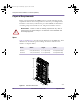
Each NPM rack is connected to the main power bay by three power cables. Table
2.9 shows the sizes of circuit breakers required to protect the power cables in the
event of a current overload or short-circuit condition.
Backup Power
The NPM basestation does not contain any internal battery backup systems.
Ensure that your main power source has a backup power system in case of a
power failure.
Power Bay Ground and Voltage Levels
Table 2.10 shows the required electrical levels as measured at the PDP terminals.
Rack Circuit Breaker Size
Radio rack 70A per feed (3)
RF rack 100A per feed (3)
Table 2.9
Power Bay Circuit Breaker Requirements
Unit Measurement Specification
Voltage +24V DC (+) to return (–) +27.5V DC nominal
(25.0V DC min, 28.0V DC max)
Power +24V DC (+) to return (–) 10kW minimum
Voltage Return (–) to ground 0.5V DC maximum
Resistance Return (–) to ground 0.1Ω maximum
Voltage +24V DC (+) to ground +25.0V to +28.5V DC
Table 2.10
Required Ground Levels
installation.book Page 30 Wednesday, August 6, 2003 6:06 PM