installation.book Page 1 Wednesday, August 6, 2003 6:06 PM Amosphere NPM Installation Procedures (MMDS) Release 1.
installation.book Page 2 Wednesday, August 6, 2003 6:06 PM Copyright 2001, 2002, 2003 SOMA Networks, Inc. All Rights Reserved. SOMA Networks, Inc. 185 Berry Street Suite 2000 San Francisco, CA 94107 U.S.A. Phone +1.415.882.6500 Fax +1.415.882.6501 SOMA, SOMA Networks and the star-and-circle logo are trademarks of SOMA Networks, Inc. All SOMA Networks product names are trademarks of SOMA Networks, Inc. All other company and product names may be trademarks or registered trademarks of their respective owners.
installation.book Page 3 Wednesday, August 6, 2003 6:06 PM Chapter 0 P REFACE This book explains how to install an Amosphere NPM basestation. Installation includes installing the racks, connecting the basestation to the network core, and powering on the system. This book is intended for field technicians with experience installing and configuring telecommunications equipment at cellular basestations and network operations centers.
installation.
installation.
installation.book Page 6 Wednesday, August 6, 2003 6:06 PM Amosphere NPM Installation Procedures (MMDS) Bits and Bytes For clarity, bits and bytes are not abbreviated in this document, but their prefixes are. SOMA Networks follows the common practice of using SI prefixes (base 10) with these terms. Thus, 1 kbit/s (kilobit per second) is equivalent to 1000 bits/s; it should not be confused with 1 Kibit/s (kilobinary bit per second) or 1 x 210 = 1024 bits/s.
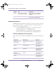
installation.book Page 7 Wednesday, August 6, 2003 6:06 PM Table 5 shows the meaning of symbols used in procedures throughout this guide.
installation.book Page 8 Wednesday, August 6, 2003 6:06 PM Amosphere NPM Installation Procedures (MMDS) Special Information Information of special importance is highlighted in the text using indentation and icons. The following examples show the special information types used in the document. They are listed in ascending order of importance. N O T E : A note contains information of special interest. C A U T I O N : A general caution is shown when there is a risk of affecting ! ! service.
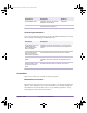
installation.book Page 9 Wednesday, August 6, 2003 6:06 PM Trademark Identification The following SOMA Networks trademarks are used without notation in the rest of this document: AmosTM software environment AmosphereTM system NPMTM basestation SOMAportTM subscriber device Tell Us How We Are Doing If you have any feedback about this document, e-mail Technical Communications at SOMA Networks: docs@somanetworks.com. Document Change History Table 6 shows the change history for this document.
installation.
installation.book Page 11 Wednesday, August 6, 2003 6:06 PM CONTENTS Chapter 1 Installation Overview ............................................................................ 19 Installation Process Summary . . . . . . . . . . . . . . . . . . . . . . . . . . . . . . . . . . . . . . . . 20 Necessary Conditions for Installation . . . . . . . . . . . . . . . . . . . . . . . . . . . . . . . . . . 21 Chapter 2 Site Preparation................................................................................
installation.book Page 12 Wednesday, August 6, 2003 6:06 PM Amosphere NPM Installation Procedures (MMDS) Attaching the Shelves and Modules .................................................................... Radio Rack Layout . . . . . . . . . . . . . . . . . . . . . . . . . . . . . . . . . . . . . . . . . . . . . . . RF Rack Layout . . . . . . . . . . . . . . . . . . . . . . . . . . . . . . . . . . . . . . . . . . . . . . . . . . Attach the Radio Shelves to the Radio Rack. . . . . . . . . . . . . . . . .
installation.book Page 13 Wednesday, August 6, 2003 6:06 PM Contents Performing the Cutover and Power-On . . . . . . . . . . . . . . . . . . . . . . . . . . . . . . . 133 Acceptance Test Plan for Basestation Upgrade . . . . . . . . . . . . . . . . . . . . . . . . . . 134 Chapter C Discontinued NPM Equipment ........................................................... 137 ZT5550 Configuration. . . . . . . . . . . . . . . . . . . . . . . . . . . . . . . . . . . . . . . . . . . . 138 ZT5541 Configuration. .
installation.
installation.book Page 15 Wednesday, August 6, 2003 6:06 PM L IST OF TABLES Chapter 0 August 6, 2003 Chapter 1 Installation Overview Table 1.1 Installation Process Summary . . . . . . . . . . . . . . . . . . . . . . . . . . . . . . . . 20 Chapter 2 Site Preparation Table 2.1 Table 2.2 Table 2.3 Table 2.4 Table 2.5 Table 2.6 Table 2.7 Table 2.8 Table 2.9 Table 2.10 Table 2.11 Table 2.12 Table 2.13 Table 2.14 Rack Dimensions . . . . . . . . . . . . . . . . . . . . . . . . . . . . . . . . . . . . .
installation.book Page 16 Wednesday, August 6, 2003 6:06 PM Amosphere NPM Installation Procedures (MMDS) Table 4.6 Table 4.7 Table 4.8 Table 4.9 Table 4.10 Table 4.11 Table 4.12 Table 4.13 Table 4.14 Table 4.15 Table 4.16 Table 4.17 Table 4.18 Table 4.19 16 Utility Shelf Layout (Rear-Facing Cards) . . . . . . . . . . . . . . . . . . . . . . . 79 Radio Shelf Layout (Front-Facing Cards). . . . . . . . . . . . . . . . . . . . . . . 80 Radio Shelf Layout (Rear-Facing Cards). . . . . . . . . . . . . . . . . .
installation.book Page 17 Wednesday, August 6, 2003 6:06 PM L IST OF F IGURES Chapter 0 Chapter 1 August 6, 2003 Installation Overview Chapter 2 Site Preparation Figure 2.1 NPM Rack Dimensions . . . . . . . . . . . . . . . . . . . . . . . . . . . . . . . . . 24 Chapter 3 Pre-Installation Activities Figure 3.1 Figure 3.2 Wrist-Strap Grounding Point . . . . . . . . . . . . . . . . . . . . . . . . . . . . . 41 Ethernet Switch Jumper Configuration . . . . . . . . . . . . . . . . . . . . .
installation.book Page 18 Wednesday, August 6, 2003 6:06 PM Amosphere NPM Installation Procedures (MMDS) Chapter 5 18 Power-On Procedures Chapter 6 On-Site Software Installation and Configuration Procedures Figure 6.1 Figure 6.2 GPS Serial Interface Adapter . . . . . . . . . . . . . . . . . . . . . . . . . . . . .120 Ethernet Switch Serial Cable . . . . . . . . . . . . . . . . . . . . . . . . . . . . . .
installation.book Page 19 Wednesday, August 6, 2003 6:06 PM Chapter 1 I NSTALLATION OVERVIEW Chapter 1 This chapter provides an overview of the installation process. Please familiarize yourself with the installation process in general before proceeding to the next chapter. Contents Installation Process Summary ................................................................................. 20 Necessary Conditions for Installation .......................................................................
installation.book Page 20 Wednesday, August 6, 2003 6:06 PM Amosphere NPM Installation Procedures (MMDS) Installation Process Summary Installation of an NPM basestation should take approximately two to three days, assuming the site already meets the requirements specified in Chapter 2, “Site Preparation”. Three people should be present during the installation, especially when moving NPM equipment. Table 1.1 lists the procedures to install an NPM basestation.
installation.book Page 21 Wednesday, August 6, 2003 6:06 PM Chapter 1: Installation Overview Necessary Conditions for Installation The installation procedures in this manual assume that the following conditions have been met: The core servers located at the network operations center (NOC) are operational and connected to the backhaul. The backhaul has been tested and is connected to the edge routers.
installation.
installation.book Page 23 Wednesday, August 6, 2003 6:06 PM Chapter 2 SITE PREPARATION Chapter 2 This chapter identifies the requirements that your site needs to meet before you can proceed with the installation of the NPM basestation. Please review these requirements before proceeding to the next chapter. Contents Physical Requirements ............................................................................................ 24 Environmental Requirements ..............................................
installation.book Page 24 Wednesday, August 6, 2003 6:06 PM Amosphere NPM Installation Procedures (MMDS) Physical Requirements Before you begin installing the NPM basestation, read the following physical requirements. Ensure that each requirement is met before proceeding with the installation, and consult your methods of procedures (MOPs) for information concerning transportation method, route, and precise installation location.
installation.book Page 25 Wednesday, August 6, 2003 6:06 PM Chapter 2: Site Preparation Weight The total weight of a 6-sector NPM basestation is approximately 544 kg (1219 pounds). The racks have a floor loading of approximately 354 kg/m2 (92 pounds/foot2), as per Telcordia Technologies GR-1275-CORE. A dolly or crane is required to move the racks. Table 2.2 shows the weight of the different NPM components. Component Weight Empty single rack 69.
installation.book Page 26 Wednesday, August 6, 2003 6:06 PM Amosphere NPM Installation Procedures (MMDS) Torque Values Table 2.3 shows the recommended torque values for the different sizes of fasteners used in the NPM racks. Fastener Size Recommended Torque #4 (0.112-inch) screw 6 inch-pounds #6 (0.138-inch) screw 12 inch-pounds #8 (0.
installation.book Page 27 Wednesday, August 6, 2003 6:06 PM Chapter 2: Site Preparation Environmental Requirements Before you begin installing the NPM basestation, read the following environmental requirements. Ensure that each requirement is met before proceeding with the installation and consult your MOPs for procedures concerning building requirements, hazardous materials and waste, and environmental systems.
installation.book Page 28 Wednesday, August 6, 2003 6:06 PM Amosphere NPM Installation Procedures (MMDS) Altitude Certain components in the NPM basestation are sensitive to altitude. Table 2.6 shows the altitude requirements for the basestation. Operational State Altitude Requirement Operating –60 m to +1800 m (–197 feet to +5904 feet) Table 2.6 Altitude Requirements Airflow Each NPM basestation rack requires 0.
installation.book Page 29 Wednesday, August 6, 2003 6:06 PM Chapter 2: Site Preparation Electrical Requirements Before you begin installing the NPM basestation, read the following requirements. Ensure that each requirement is met before proceeding with the installation and consult your MOPs for procedures concerning power, grounding, and high-risk cut-over activities.
installation.book Page 30 Wednesday, August 6, 2003 6:06 PM Amosphere NPM Installation Procedures (MMDS) Main Power Bay Circuit Breaker Size Each NPM rack is connected to the main power bay by three power cables. Table 2.9 shows the sizes of circuit breakers required to protect the power cables in the event of a current overload or short-circuit condition. Rack Circuit Breaker Size Radio rack 70A per feed (3) RF rack 100A per feed (3) Table 2.
installation.book Page 31 Wednesday, August 6, 2003 6:06 PM Chapter 2: Site Preparation NPM Circuit Breaker Current Loads Each NPM rack contains a power distribution panel (PDP). The PDP has up to 16 circuit breakers (CBs). Each breaker switch controls the power to a specific NPM component. Individual NPM components can be powered off by setting the appropriate breaker switch to the OFF (down) position. Table 2.11 shows the maximum current loading of the circuit breakers in the RFSS and radio rack PDPs.
installation.book Page 32 Wednesday, August 6, 2003 6:06 PM Amosphere NPM Installation Procedures (MMDS) Rack Grounds Table 2.12 shows the grounding requirements for each rack. Ground Type Requirement Frame ground Each NPM rack requires one connection to its frame assembly for use as a frame ground. The frame ground cable uses #6 AWG wire. Main ground Each NPM rack requires one connection to the main building ground, such as the master ground bar (MGB). The ground cable uses #6 AWG wire.
installation.book Page 33 Wednesday, August 6, 2003 6:06 PM Chapter 2: Site Preparation Network and Backhaul Requirements Before you begin installing the NPM basestation, see the Amosphere System Overview for a description of network requirements and consult your field engineering package (FEP) for information involving the network equipment. PSTN Gateway The NPM basestation does not connect directly to the PSTN.
installation.book Page 34 Wednesday, August 6, 2003 6:06 PM Amosphere NPM Installation Procedures (MMDS) Core Servers See your core server field engineering package (FEP) for connectivity information.
installation.book Page 35 Wednesday, August 6, 2003 6:06 PM Chapter 2: Site Preparation Site Requirements Each site has unique requirements and characteristics. See your field engineering package (FEP) for specific requirements relating to your installation.
installation.book Page 36 Wednesday, August 6, 2003 6:06 PM Amosphere NPM Installation Procedures (MMDS) Antenna Mounting Locations The NPM basestation uses two antennas (main and diversity) per sector. Ensure that your tower can support the number of antennas shown in Table 2.14. Sectors Supported by Basestation Required Antennas 1 2 2 4 3 6 4 8 5 10 6 12 Table 2.
installation.book Page 37 Wednesday, August 6, 2003 6:06 PM Chapter 2: Site Preparation Isolated Ground Plane Environment Ensure that the NPM basestation will be installed in an isolated ground plane environment as defined in Telcordia Technologies GR-1275-CORE. Master Ground Bar Requirements The site’s master ground bar (MGB) must be connected to the building principal ground’s electrode system.
installation.book Page 38 Wednesday, August 6, 2003 6:06 PM Amosphere NPM Installation Procedures (MMDS) Ground Resistance The resistance of the building principal ground should be as low as practically possible (typically less than 5Ω). Under no circumstances should the resistance exceed the local electrical utility limits of 25Ω (NEC article 250-56, 1999). Additional Site Requirements See Telcordia Technologies GR-1275-CORE for a comprehensive description of generic site requirements.
installation.book Page 39 Wednesday, August 6, 2003 6:06 PM Chapter 3 PRE-INSTALLATION ACTIVITIES Chapter 3 This chapter lists the tools and equipment required for installing and testing the NPM equipment. It also provides procedures for unpacking the racks and configuring individual cards and shelves. Contents Preparing for Installation .......................................................................................... 40 Configuring Cards and Shelves ............................................
installation.book Page 40 Wednesday, August 6, 2003 6:06 PM Amosphere NPM Installation Procedures (MMDS) PREPARING FOR INSTALLATION This section describes precautions, equipment, and tasks that should be reviewed or performed prior to beginning the NPM basestation installation. Table 3.1 shows the topics described in this section. Topics Page Antistatic Precautions 41 Equipment, Tools, and Supplies Checklists 42 Unpack the Equipment 44 Review Site Deliverables List 45 Table 3.
installation.book Page 41 Wednesday, August 6, 2003 6:06 PM Chapter 3: Pre-Installation Activities Antistatic Precautions W A R N I N G : Components in the NPM basestation are highly sensitive to electrostatic discharges (ESD). Follow the procedures described below to prevent unseen damage from occurring.
installation.
installation.book Page 43 Wednesday, August 6, 2003 6:06 PM Chapter 3: Pre-Installation Activities Safety Equipment The following safety equipment is recommended for a typical NPM basestation installation. Ear plugs Flashlight Electrical gloves Portable eye-wash station ESD straps Safety glasses First aid kit Safety shoes Test Equipment Table 3.2 shows the equipment recommended for testing NPM basestation functionality.
installation.book Page 44 Wednesday, August 6, 2003 6:06 PM Amosphere NPM Installation Procedures (MMDS) Unpack the Equipment The NPM racks are delivered on shipping pallets. Each rack is secured in an upright position and is bolted to the pallet. Additional equipment is delivered in separate shipping boxes. To unpack the NPM equipment 1 Transport the shipping boxes to the installation area using a dolly or pallet jack.
installation.book Page 45 Wednesday, August 6, 2003 6:06 PM Chapter 3: Pre-Installation Activities Review Site Deliverables List Table 3.3 shows the paperwork that ships with each NPM basestation. Document Description Anchor kit Lists installation kit contents NPM BOM Lists every component in the basestation Shelf inspection checklist Factory inspection of each utility and radio shelf Table 3.
installation.book Page 46 Wednesday, August 6, 2003 6:06 PM Amosphere NPM Installation Procedures (MMDS) CONFIGURING CARDS AND SHELVES Some of the jumpers and switches on the cards and shelves in the NPM basestation require configurations which differ from the factory defaults. This section provides the procedures for making the necessary alterations. Table 3.4 shows the actions described in this section. Action Page Configure Ethernet Switch Jumpers 47 Table 3.
installation.book Page 47 Wednesday, August 6, 2003 6:06 PM Chapter 3: Pre-Installation Activities Configure Ethernet Switch Jumpers It may be necessary to modify the jumpers on the Ethernet switches. The NPM basestation uses a configuration of the Ethernet switches that differs from the manufacturer’s original settings. N O T E : If the Ethernet switches are pre-installed in the shelves, then they have already been configured and this procedure is not required. Table 3.
installation.book Page 48 Wednesday, August 6, 2003 6:06 PM Amosphere NPM Installation Procedures (MMDS) To configure the Ethernet switches 1 Remove the two Ethernet switches from their antistatic packaging at a grounded work area. Ensure that you are properly grounded with a wrist or boot strap before handling the cards. 2 Remove the K1 PCI Reset jumper from each card. Figure 3.2 shows the location of the jumper. K1 PCI Reset Jumper K7 CPCI BDSEL 00275 Figure 3.