
User Manual

August 6, 2003 Part 004071A revision 00b 101
Chapter 4: Installation Procedures
Connect the RF Cables
The RF cables are 0.195-inch coaxial cables with male SMA connectors on each
end.
Component Numbering
The RF shelves are numbered from bottom to top (that is, the bottom shelf is “0”
and the top shelf is “2”). When viewed from the front of the NPM basestation,
the RFSS modules in each shelf are numbered from left to right (that is, the left
module is “0” and the right module is “3”).
The radio shelves are numbered from bottom to top (that is, the bottom shelf is
“0” and the top shelf is “2”). Each radio shelf contains two IF/RF cards, one in
slots 10–11 and one in slots 15–16.
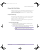
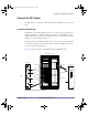
Figure 4.19 shows the layout of the RFSS modules and IF/RF cards.
Figure 4.19
RF Connector Locations
RFSS
[TT LNA]
Rx
Tx
SGNL
FAIL
ACTIVE
FUSE
0
Rx
00558
123
0123
0123
Utility shelf
RF Shelf #0
RF Shelf #1
RF Shelf #2
Radio Shelf #2
Radio Shelf #1
RX MAIN
RX DIV
TX MAIN
TX DIV
Radio Shelf #0
Tx
IF/RF Card
RFSS Module
NPM Racks (Front View)
installation.book Page 101 Wednesday, August 6, 2003 6:06 PM