
User Manual

August 6, 2003 Part 004071A revision 00b 99
Chapter 4: Installation Procedures
Connect the Clock Cables
The GPS clock module receives its timing signals from the GPS antennas via two
coaxial cables with male TNC connectors on each end. The clock cables use
0.195-inch coaxial cables with male SMA connectors to distribute the timing
signals to the clock wiring cards.
Component Numbering
The radio shelves are numbered from bottom to top (that is, the bottom shelf is
“0” and the top shelf is “2”). Each radio shelf contains two rear-facing clock
wiring cards, one in slot 11 and one in slot 16.
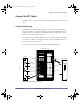
The GPS clock module outputs are numbered from left to right when viewed
from the back of the NPM basestation.
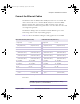
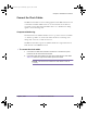
To connect the clock cables
1 Connect the two GPS antenna cables to the Antenna 1 and Antenna 2 ports
located on the rear of the GPS clock module.
2 Connect the GPS clock module to the clock wiring cards using the clock cables.
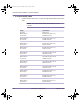
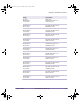
Table 4.16 shows the origin and termination point of each cable.
NOTE: The minimum bend radius for clock cables is 2.54 cm
(1.0 inch).
installation.book Page 99 Wednesday, August 6, 2003 6:06 PM