
User Manual


96 Part 004071A revision 00b August 6, 2003
Amosphere NPM Installation Procedures (MMDS)
Connect the Alarm Cables
The alarm cables are serial cables with DSUB connectors on each end. The
DSUB connectors are secured to their receptacles with 1/8-inch flathead screws.
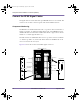
To connect the alarm cables
1 Ensure that the main +24V DC power supply is powered off.
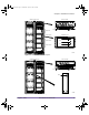
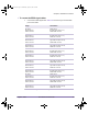
2 Connect the alarm cables to the alarm wiring card. Table 4.14 shows the origin
and termination point of each cable.
WARNING: Ensure that the main +24V DC power supply for the NPM
basestation is powered off before connecting the alarm cables. The PDP
alarm cables are hot at all times and are not hot-swappable, even when the
circuit breakers in the PDP are powered OFF (down). Failure to power off the
main +24V DC power supply may result in damage to the cables and
basestation.
The PDP alarm cables are not hot-swappable. Do not disconnect a PDP
alarm cable (labeled “RADIO PDP” or “RF PDP”) from the alarm wiring
card if the basestation is receiving +24V DC or if the fuses in the PDP
have not been temporarily removed.
Origin Termination
Alarm wiring card (slots 12–13),
UPPER COOLING RF connector
RF rack, upper cooling unit,
SIGNAL connector
Alarm wiring card (slots 12–13),
UPPER COOLING RADIO connector
Radio rack, upper cooling unit,
SIGNAL connector
Alarm wiring card (slots 12–13),
LOWER COOLING RF connector
RF rack, lower cooling unit,
SIGNAL connector
Alarm wiring card (slots 12–13),
LOWER COOLING RADIO connector
Radio rack, lower cooling unit,
SIGNAL connector
Alarm wiring card (slots 12–13),
RF PDP connector
RF rack, PDP SGNL connector
(left-most connector)
Alarm wiring card (slots 12–13),
RADIO PDP connector
Radio rack, PDP SGNL connector
(left-most connector)
Table 4.14
Alarm Cable Summary
installation.book Page 96 Wednesday, August 6, 2003 6:06 PM