
User Manual

94 Part 004071A revision 00b August 6, 2003
Amosphere NPM Installation Procedures (MMDS)
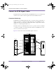
Connect the RFSS Signal Cables
The signal cables are serial cables with 9-pin DSUB connectors on each end. The
connectors are secured to their receptacles with 1/8-inch flathead screws.
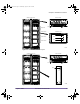
Component Numbering
The RF shelves are numbered from bottom to top (that is, the bottom shelf is “0”
and the top shelf is “2”). When viewed from the front of the NPM basestation,
the RFSS modules in each shelf are numbered from left to right (that is, the left
module is “0” and the right module is “3”).
The radio shelves are numbered from bottom to top (that is, the bottom shelf is
“0” and the top shelf is “2”). Each radio shelf contains two IF/RF cards, one in
slots 10–11 and one in slots 15–16.
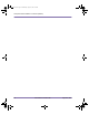
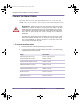
Figure 4.18 shows the location of the RFSS signal connectors.
Figure 4.18
RFSS Signal Connector Layout
0
SGNL
00557
123
0123
0123
RFSS
[TT LNA]
Rx
Tx
SGNL
FAIL
ACTIVE
FUSE
Utility shelf
RF Shelf #0
RF Shelf #1
RF Shelf #2
Radio Shelf #2
Radio Shelf #1
Radio Shelf #0
SGNL MAIN
SGNL DIV
IF/RF Card
RFSS Module
NPM Racks (Front View)
installation.book Page 94 Wednesday, August 6, 2003 6:06 PM