
User Manual

92 Part 004071A revision 00b August 6, 2003
Amosphere NPM Installation Procedures (MMDS)
To connect the PDP power cables
1 Ensure that each PDP circuit breaker in the radio and RF rack is in the OFF
(down) position.
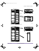
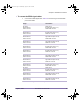
2 Connect each PDP power cable in the radio rack. Table 4.11 shows the origin and
termination point of each cable.
Origin Termination
Radio rack PDP, CB 01 Lower cooling unit
Radio rack PDP, CB 02 Radio shelf 0 (bottom), PS0
Radio rack PDP, CB 03 Radio shelf 0 (bottom), PS1
Radio rack PDP, CB 04 Radio shelf 0 (bottom), PS2
Radio rack PDP, CB 05 Radio shelf 1 (middle), PS0
Radio rack PDP, CB 06 Radio shelf 1 (middle), PS1
Radio rack PDP, CB 07 Radio shelf 1 (middle), PS2
Radio rack PDP, CB 08 Radio shelf 2 (top), PS0
Radio rack PDP, CB 09 Radio shelf 2 (top), PS1
Radio rack PDP, CB 10 Radio shelf 2 (top), PS2
Radio rack PDP, CB 11 Utility shelf, PS0
Radio rack PDP, CB 12 Utility shelf, PS1
Radio rack PDP, CB 13 Utility shelf, PS2
Radio rack PDP, CB 14 Upper cooling unit
Radio rack PDP, CB 15 GPS clock module
Table 4.11
Radio Rack Power Cable Summary
installation.book Page 92 Wednesday, August 6, 2003 6:06 PM