
User Manual


86 Part 004071A revision 00b August 6, 2003
Amosphere NPM Installation Procedures (MMDS)
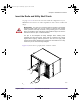
To insert the cards into the utility and radio shelves
1 Ensure that there are no obstructions in the slot or on the guide rails and check the
backplane for bent pins.
If there are bent pins, the backplane is damaged and requires repair. Report any
damaged equipment to your field support coordinator as soon as possible.
2 Remove the card from its antistatic bag.
3 Set the two ejector handles on the card in the open position by turning the handles
away from the center of the front panel.
In the open position, the ejector handles are at an approximately 45°
angle from
the front panel.
4 Ensure that the mounting screws are withdrawn enough to allow for the insertion
of the card.
Single-slot cards have two mounting screws, one located under each ejector
handle. Double-slot cards have four mounting screws, one located under each
ejector handle and one located beside each ejector handle.
5 Orient the card so that the text on the front panel is right-side up. The guide pins
should be located to the right of the ejector handles.
6 Slide the card into the correct slot. Slot locations are shown on pages 78 to 81.
Use the guide rails to ensure the connectors are aligned.
7 Apply sufficient pressure to fully mate the card by pressing on both ejector handles
with equal force. If present on the card, the guide pins should slide into the round
holes located at the top and the bottom of each slot on the right-hand side.
8 Lock the card in the slot by turning the ejector handles towards the center of the
front panel.
In the lock position, the ejector handles are at a 90° angle from the front panel.
9 Secure the card in the slot by installing the 2.5-mm mounting screws. Torque each
screw to 4 inch-pounds.
10 Repeat steps 1 to 9 for the remaining cards.
installation.book Page 86 Wednesday, August 6, 2003 6:06 PM