installation.book Page 49 Wednesday, August 6, 2003 6:06 PM Chapter 4 INSTALLATION PROCEDURES Chapter 4 This chapter provides procedures for installing the racks and their internal components. It also provides an overview about installing the antennas used with the NPM basestation. Before proceeding with this chapter, you must complete all the tasks described in Chapter 3. Contents Installing the NPM Racks .........................................................................................
installation.
installation.book Page 51 Wednesday, August 6, 2003 6:06 PM Chapter 4: Installation Procedures INSTALLING THE NPM RACKS These procedures describe how to prepare the floor for rack installation, move the racks into place, and secure the racks to each other, to the floor, and to the ceiling. Table 4.1 shows the actions described in this section. Action Page Prepare the Installation Location 52 Position the Racks 54 Secure the Racks 55 Table 4.
installation.book Page 52 Wednesday, August 6, 2003 6:06 PM Amosphere NPM Installation Procedures (MMDS) Prepare the Installation Location This procedure applies to installing the NPM basestation on a concrete floor and securing the racks using 4-inch concrete expansion bolts (called anchor bolts in this document). These anchor bolts are designed for sites in level 4 seismic zones and may not be suitable for your site.
installation.book Page 53 Wednesday, August 6, 2003 6:06 PM Chapter 4: Installation Procedures 10 Clean each anchor hole thoroughly using a vacuum cleaner with a narrow nozzle attachment that can reach into the hole and remove the debris. 11 Cover the anchor holes with tape to prevent debris from entering them. 12 Repeat steps 3 to 11 for the second rack.
installation.book Page 54 Wednesday, August 6, 2003 6:06 PM Amosphere NPM Installation Procedures (MMDS) Position the Racks This procedure describes how to position and level the racks. To position the racks 1 Install two eyelet bolts in the top of each rack if you intend to use a crane to move the racks. 2 If you are using anchor bolts, remove the tape from the anchor holes.
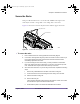
installation.book Page 55 Wednesday, August 6, 2003 6:06 PM Chapter 4: Installation Procedures Secure the Racks This procedure describes how to secure the radio and RF racks in place. The racks may be secured to the ground, to the ceiling, and to each other. Figure 4.2 shows the location of the junction bar and the support bolt holes. Support Bolt Holes Junction Bar 00554 Figure 4.
installation.book Page 56 Wednesday, August 6, 2003 6:06 PM Amosphere NPM Installation Procedures (MMDS) vi Ensure that the anchor bolt, spacer sleeve, expansion sleeve, and expansion cone do not have any slack. If any of these parts are loose, tighten the parts by hand to remove any slack. Do not start spreading the expansion sleeve. vii Place a hold-down plate over the holes in the base of each rack.
installation.book Page 57 Wednesday, August 6, 2003 6:06 PM Chapter 4: Installation Procedures ATTACHING GROUND AND POWER CABLES These procedures describe how to ground and power the NPM basestation. Table 4.2 shows the actions described in this section. Action Page Check PDP Sector Configuration 58 Ground the NPM Racks 59 Attach the Main and Return Power Cables 61 Test Power Supply Voltage and Ground 63 Table 4.
installation.book Page 58 Wednesday, August 6, 2003 6:06 PM Amosphere NPM Installation Procedures (MMDS) Check PDP Sector Configuration The PDP sector configuration switch, located inside the PDP, configures the circuit breakers to support a specific number of radio sectors (1–6). In an NPM basestation supporting fewer than six sectors, some of the circuit breakers are not used and are therefore left in the OFF (down) position.
installation.book Page 59 Wednesday, August 6, 2003 6:06 PM Chapter 4: Installation Procedures Ground the NPM Racks Each rack requires a ground cable connecting the PDP to the building’s grounding system. A frame ground cable connects the NPM frame to the PDP, ensuring that the frame and its attached components are grounded. Figure 4.4 shows the cables used to ground the racks. For clarity, the PDP rear cover is not depicted. Frame Ground Cable Main Ground Cable 00279 Figure 4.
installation.book Page 60 Wednesday, August 6, 2003 6:06 PM Amosphere NPM Installation Procedures (MMDS) Figure 4.5 shows the dimensions of the compression lugs. 1/4" Hole 5/8" Figure 4.5 00280 Compression Lug Dimensions 5 Apply an anti-oxidant solution to the ground terminals on the PDP. 6 Connect the compression lug on the main ground cable to one of the two ground terminals, as shown in Figure 4.6. Use a 1/4-inch hex nut with a 1/4-inch split-lock washer when securing the cable.
installation.book Page 61 Wednesday, August 6, 2003 6:06 PM Chapter 4: Installation Procedures Attach the Main and Return Power Cables Refer to the MOPs before scheduling or beginning any work involving the site’s main power. Before proceeding with this procedure, ensure that all the necessary site cable layout, runaway, and grid work has been completed. W A R N I N G : Ensure that the necessary requirements and procedures have been reviewed prior to the start of any power-related activity.
installation.book Page 62 Wednesday, August 6, 2003 6:06 PM Amosphere NPM Installation Procedures (MMDS) +24V Main Power Terminals Return Power Terminals 00282 Figure 4.7 Main and Return Power Terminals 10 Ensure the main and return power cables are connected to the main power supply correctly by performing a continuity test on each cable. 11 Dress and label the main and return power cables according to the standards and requirements of your site.
installation.book Page 63 Wednesday, August 6, 2003 6:06 PM Chapter 4: Installation Procedures Test Power Supply Voltage and Ground This procedure tests the voltage levels and grounds of the NPM basestation and the main power supply. The test ensures that the main power supply is providing +24V DC and that the power supply and racks are properly grounded. Figure 4.8 shows the pins of the basestation power cables.
installation.book Page 64 Wednesday, August 6, 2003 6:06 PM Amosphere NPM Installation Procedures (MMDS) ii Observe the voltage reading on the multimeter. The voltage should be less than 0.5mV from 0. If the voltage is greater than ±0.5mV, there may be a grounding problem. See the documentation that ships with your power supply for troubleshooting procedures. Do not power on the basestation until the problem has been resolved.
installation.book Page 65 Wednesday, August 6, 2003 6:06 PM Chapter 4: Installation Procedures 9 If all the tests described in steps 5–8 passed, then the rack is properly grounded and the main power supply is operating correctly. If any if the tests failed, investigate and correct the problem. Repeat this procedure after corrective action is taken. Do not power on the basestation if any of the tests failed. 10 Disconnect both probes from the power cable.
installation.
installation.book Page 67 Wednesday, August 6, 2003 6:06 PM Chapter 4: Installation Procedures ATTACHING THE SHELVES AND MODULES These procedures describe how to attach the shelves and modules to the NPM racks. Table 4.3 shows the actions described in this section. Action Page Attach the Radio Shelves to the Radio Rack 70 Cover Empty Radio Bays 71 Attach the Utility Shelf to the Radio Rack 72 Install the GPS Clock Module 73 Install the RFSS Modules 74 Cover Empty RFSS Slots 75 Table 4.
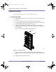
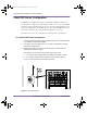
installation.book Page 68 Wednesday, August 6, 2003 6:06 PM Amosphere NPM Installation Procedures (MMDS) Radio Rack Layout The utility and radio shelves and the GPS clock module slide into their respective bays and bolt directly to the rack using 5/16-inch screws. The recommended torque value for each 5/16-inch screw is 50 inch-pounds. Figure 4.9 shows the layout of the radio rack.
installation.book Page 69 Wednesday, August 6, 2003 6:06 PM Chapter 4: Installation Procedures RF Rack Layout The RFSS modules slide into their respective slots and bolt to each RF shelf using #2 Phillips thumb screws. In basestations that have less than 12 RFSS modules, the empty slots are covered with filler panels. Figure 4.10 shows the location of the RFSS modules and filler panels in a basestation that supports three sectors.
installation.book Page 70 Wednesday, August 6, 2003 6:06 PM Amosphere NPM Installation Procedures (MMDS) Attach the Radio Shelves to the Radio Rack Depending on the configuration of your NPM basestation, there may be one, two, or three radio shelves that need to be installed. The radio shelves are installed in the bottom three bays in the radio rack. If your basestation uses fewer than three radio shelves, you need to add dummy shelves to the empty bays to ensure the required airflow to the occupied bays.
installation.book Page 71 Wednesday, August 6, 2003 6:06 PM Chapter 4: Installation Procedures Cover Empty Radio Bays Depending on the configuration of your NPM basestation, there may be empty bays on the radio rack. Your basestation may arrive with the unused radio bays already occupied with dummy shelves. If this is not the case or if the configuration of your basestation has changed, you need to add dummy shelves to any empty bays to ensure the required airflow to the occupied bays.
installation.book Page 72 Wednesday, August 6, 2003 6:06 PM Amosphere NPM Installation Procedures (MMDS) Attach the Utility Shelf to the Radio Rack The utility shelf is installed in the top-most bay in the radio rack. To attach the utility shelf to the radio rack 1 Remove the utility shelf from its protective bag. You can distinguish the utility shelf from the radio shelves by reading the manufacturer’s label on the inside of the shelf. 2 Slide the utility shelf into the top bay in the radio rack.
installation.book Page 73 Wednesday, August 6, 2003 6:06 PM Chapter 4: Installation Procedures Install the GPS Clock Module The Global Positioning System (GPS) clock module consists of a 1U module that contains two plug-in GPS receivers. The GPS clock module requires two GPS antennas. GPS antenna installation is described on page 106. To install the GPS clock module 1 Remove the GPS clock module from its antistatic packaging.
installation.book Page 74 Wednesday, August 6, 2003 6:06 PM Amosphere NPM Installation Procedures (MMDS) Install the RFSS Modules If the configuration of your NPM basestation does not require a full complement of RFSS modules, some slots may be covered with filler panels. CAUTION: Each RFSS module weighs approximately 14.1 kg (31 pounds). ! To insert the RFSS modules in the RF rack 1 Remove the RFSS module from its protective bag.
installation.book Page 75 Wednesday, August 6, 2003 6:06 PM Chapter 4: Installation Procedures Cover Empty RFSS Slots Any empty slots in the RF shelves should be covered with RFSS filler panels. The RFSS filler panels protect the other RFSS modules from dust and ensure the required air flow to the installed RFSS modules. To cover unused slots with RFSS filler panels 1 Remove the RFSS filler panel from its protective bag. 2 Orient the filler panel so that the text on the front panel is right-side up.
installation.