
User Manual

120 Part 004071A revision 00b August 6, 2003
Amosphere NPM Installation Procedures (MMDS)
Optimize the GPS Clock Module
To ensure accurate timing, you must optimize the operation of the GPS clock
module. Optimizing the operation of the GPS clock module involves
compensating for the signal delay caused by the length of the GPS antenna
wiring.
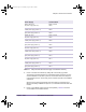
Consult with your cable manufacturer for the delay characteristics of your cable
type. You need to express the delay values in nanoseconds per meter (ns/m).
NOTE: Different lengths and types of cables may be used, as
long as the signal loss at 1575 MHz is less than 30 dB.
See the Zyfer AccuSync-R GPS Synchronized Time and
Frequency Instrument User’s Manual for the average delay
values of common types of GPS antenna cabling.
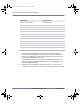
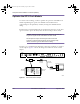
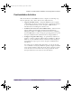
In order to use a standard serial cable when connecting a terminal, you require a
custom adapter. Figure 6.1 shows the wiring and connections for the custom
adapter.
Figure 6.1
GPS Serial Interface Adapter
00330
FREQUENCY OUT
PULSE OUT
TTL
ANTENNA
TPPS
TTL
ALARM
12
CONTROL
POWER
19 TO 30 Vdc
2 AMP MAX
+
TTL
2
3
5
1
9
2
3
5
4
6
7
8
TXD (out)
RXD (in)
GND
RCD (in)
RI (in)
RXD (in)
TXD (out)
GND
DTR (out)
DSR (in)
RTS (out)
CTS (in)
Custom Adapter
DB9 Male
Connector
DB9 Female
Connector
DB9 Female
Connector
DB9 Male
Connector
Standard
Serial Cable
Diagnostic Access Port
installation.book Page 120 Wednesday, August 6, 2003 6:06 PM