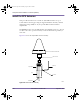
installation.book Page 106 Wednesday, August 6, 2003 6:06 PM Amosphere NPM Installation Procedures (MMDS) Install the GPS Antennas This procedure describes how to install two Zyfer GPS antennas on top of 1-inch-diameter, hollow pipes using the supplied hardware. Consult your field engineering package (FEP) for any site-specific GPS antenna installation requirements.
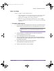
installation.book Page 107 Wednesday, August 6, 2003 6:06 PM Chapter 4: Installation Procedures Before You Begin Before you begin to install the GPS antennas: Select an installation location away from any objects that might obstruct satellite visibility to 10° of the horizon. Obstructions may cause a degradation of the GPS clock module’s performance. Ensure that the type and length of cabling used to connect the GPS antenna to the GPS clock module meets your attenuation and shielding requirements.
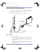
installation.book Page 108 Wednesday, August 6, 2003 6:06 PM Amosphere NPM Installation Procedures (MMDS) Install the Main and Diversity Antennas This procedure describes the general process for installing the main and diversity antennas. Consult your field engineering package (FEP) for any site-specific antenna installation requirements. Figure 4.21 shows the configuration of the main or diversity antenna).
installation.book Page 109 Wednesday, August 6, 2003 6:06 PM Chapter 4: Installation Procedures To install the main and diversity antennas 1 Verify that you have the right type of antennas, both in terms of frequency and direction. 2 Run the antenna cable from the NPM racks to the intended location of each antenna. See your field engineering package (FEP) and installation MOP for antenna cable specifics.
installation.book Page 110 Wednesday, August 6, 2003 6:06 PM Amosphere NPM Installation Procedures (MMDS) each 7/16 DIN connector to 17 foot-pounds and ensure each connector is properly weatherproofed. CAUTION: ! 110 Do not over-tighten connectors. Overtightening the connectors may damage the cable and degrade the RF signal. iv Connect the BTS port on each bias tee to the ANT port on each RFSS module. The ANT port is located on the rear side of the RFSS module.
installation.book Page 111 Wednesday, August 6, 2003 6:06 PM Chapter 4: Installation Procedures Measuring VSWR and Return Loss Voltage standing wave ratio (VSWR) is a ratio of the maximum to minimum voltage as measured along the length of a mismatched RF transmission line. VSWR indicates the level of impedance matching between RF equipment (such as amplifiers, cabling, and antennas).
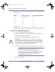
installation.book Page 112 Wednesday, August 6, 2003 6:06 PM Amosphere NPM Installation Procedures (MMDS) Table 4.19 shows the correlation between VSWR, return loss, and the percentage of reflected power. VSWR Return Loss (dB) Power Being Reflected (%) 1:1 N/A (infinite value) 0 1.25:1 19.1 1.2 1.5:1 14 4.0 1.75:1 11.3 7.4 2:1 9.5 11.1 5:1 3.5 44.7 N/A (infinite value) 0 100.0 Table 4.
installation.book Page 113 Wednesday, August 6, 2003 6:06 PM Chapter 4: Installation Procedures See the documentation that comes with your analyzer for information about performing the cable sweep and interpreting the results. 6 Record the results from the cable sweeps according to the MOPs of your site. Keeping records of periodic cable sweeps makes troubleshooting future problems easier. 7 Carefully disconnect the analyzer from the RF equipment.
installation.book Page 114 Wednesday, August 6, 2003 6:06 PM Amosphere NPM Installation Procedures (MMDS) Measuring the Distance to a Fault Distance to fault (DTF) is a measurement of VSWR or return loss based on distance. A DTF test indicates the distance to a short, open, or load. Perform a DTF test whenever a VSWR test reveals that the antenna system is not operating within specifications.
installation.book Page 115 Wednesday, August 6, 2003 6:06 PM Chapter 5 POWER-ON PROCEDURES Chapter 5 This chapter provides step-by-step procedures for powering on the NPM basestation and verifying basic functionality. Contents Power On the Basestation .....................................................................................
installation.book Page 116 Wednesday, August 6, 2003 6:06 PM Amosphere NPM Installation Procedures (MMDS) Power On the Basestation The power for the NPM basestation is controlled by circuit breakers in the PDP, located at the top of each rack. Each power supply, RFSS module, cooling unit, and GPS clock module has its own circuit breaker, which means it can be powered on and off independently of the other devices.
installation.
installation.
installation.book Page 119 Wednesday, August 6, 2003 6:06 PM Chapter 6 ON-SITE SOFTWARE INSTALLATION AND C ONFIGURATION P ROCEDURES Chapter 6 This chapter describes how to optimize the individual cards in the NPM basestation and explains the remaining steps required to make the basestation fully operation. Contents Optimize the GPS Clock Module ........................................................................... 120 Configure the Ethernet Switches .................................................
installation.book Page 120 Wednesday, August 6, 2003 6:06 PM Amosphere NPM Installation Procedures (MMDS) Optimize the GPS Clock Module To ensure accurate timing, you must optimize the operation of the GPS clock module. Optimizing the operation of the GPS clock module involves compensating for the signal delay caused by the length of the GPS antenna wiring. Consult with your cable manufacturer for the delay characteristics of your cable type.
installation.book Page 121 Wednesday, August 6, 2003 6:06 PM Chapter 6: On-Site Software Installation and Configuration Procedures To optimize the GPS clock module 1 Connect a PC to the GPS clock module using a custom adapter and a standard serial cable. N O T E : Using a standard serial or null modem cable without a custom adapter will not work. 2 Start a serial terminal session using the settings shown in Table 6.1.
installation.book Page 122 Wednesday, August 6, 2003 6:06 PM Amosphere NPM Installation Procedures (MMDS) Configure the Ethernet Switches In order to operate in the NPM basestation, the Ethernet switches require custom settings. You need to configure the Ethernet switches only once; the configuration is stored in the switch’s nonvolatile memory. You can connect to the Ethernet switch by connecting a custom serial cable with a null modem adapter to the console port located on the front panel. Figure 6.
installation.book Page 123 Wednesday, August 6, 2003 6:06 PM Chapter 6: On-Site Software Installation and Configuration Procedures To configure the Ethernet switches 1 Establish a serial connection with the Ethernet switch: i Connect a PC to the Ethernet switch using the supplied RJ-11 to DB-9 serial cable with a null modem adapter. See Table 6.2 for pin assignments. ii Start a serial terminal session using the settings shown in Table 6.3.
installation.book Page 124 Wednesday, August 6, 2003 6:06 PM Amosphere NPM Installation Procedures (MMDS) save ↵ save ↵ where: switch_name is either sw0 or sw1 switch_ip_address is the IP address of the Ethernet switch router0-0_ip_address is the IP address of the primary router 6 Reboot the Ethernet switch by typing: switch reset ↵ 7 124 Repeat steps 1 to 6 for the other Ethernet switch.
installation.book Page 125 Wednesday, August 6, 2003 6:06 PM Chapter 6: On-Site Software Installation and Configuration Procedures Post-Installation Activities After the installation of the NPM basestation is complete, the following steps may be required in order to make the basestation fully functional: Upgrade the NPM software – Amosphere NPM software is typically pre-installed at the factory. It may be necessary to upgrade the software to achieve full functionality.
installation.
installation.book Page 127 Wednesday, August 6, 2003 6:06 PM Appendix A NPM DECOMMISSIONING Chapter A This appendix describes how to safely take an NPM basestation out of service. Contents Decommissioning a Basestation ............................................................................
installation.book Page 128 Wednesday, August 6, 2003 6:06 PM Amosphere NPM Installation Procedures (MMDS) Decommissioning a Basestation Decommissioning occurs whenever a basestation is taken out of service or moved to a new location. W A R N I N G : Ensure that the necessary requirements and procedures have been reviewed prior to the start of any power-related activity. Refer to your power cut-over MOP for procedures specific to your site.
installation.book Page 129 Wednesday, August 6, 2003 6:06 PM Appendix B ADDING ADDITIONAL SECTORS Chapter B This appendix describes how to add additional sectors to an NPM basestation to increase capacity. Contents Pre-Upgrade Preparation ....................................................................................... 130 Adding Sectors to a Basestation ............................................................................ 132 Performing the Cutover and Power-On ............................
installation.book Page 130 Wednesday, August 6, 2003 6:06 PM Amosphere NPM Installation Procedures (MMDS) Pre-Upgrade Preparation Before you begin upgrading the NPM basestation, ensure that the following preparations are performed. These preparations are intended to minimize the interruption of service. Site-Specific Documentation Before upgrading the basestation, ensure that the documentation described in Table B.1 is updated, reviewed, and verified.
installation.book Page 131 Wednesday, August 6, 2003 6:06 PM : Adding Additional Sectors HVAC Requirements Ensure that the heating, ventilation, and air-conditioning (HVAC) system for the site has the capacity to handle the additional heat produced by the additional sectors. See “Heat Output” on page 28 for information. Main and Backup Power Supplies Ensure that the power supplies for the site have the capacity to handle the additional sectors. See “Electrical Requirements” on page 29 for information.
installation.book Page 132 Wednesday, August 6, 2003 6:06 PM Amosphere NPM Installation Procedures (MMDS) Adding Sectors to a Basestation This procedure describes how to add additional sectors to a basestation. See your updated field engineering package (FEP) for site-specific information about the upgrade. To add sectors to a Basestation 132 1 Install any additional radio shelves. See “Attach the Radio Shelves to the Radio Rack” on page 70.
installation.book Page 133 Wednesday, August 6, 2003 6:06 PM : Adding Additional Sectors Performing the Cutover and Power-On Switching to the new antenna configuration will result in a service interruption. The cutover should occur during a scheduled maintenance window. C A U T I O N : Before performing this procedure, ensure that a quality audit has been performed on the system, as described in “Adding Sectors to a Basestation” on page 132. ! This procedure will cause a service interruption.
installation.book Page 134 Wednesday, August 6, 2003 6:06 PM Amosphere NPM Installation Procedures (MMDS) Acceptance Test Plan for Basestation Upgrade After completing the upgrade, review the acceptance test plan (ATP) to verify the functionality and performance of the new configuration.
installation.book Page 135 Wednesday, August 6, 2003 6:06 PM : Adding Additional Sectors In situations where a configuration change for a large number of sites is planned, sector upgrades should occur in several phases. The entire network should be divided in clusters of sites and sectorization performed for each cluster individually. Coverage optimization should be performed for each cluster after sectorization is completed.
installation.
installation.book Page 137 Wednesday, August 6, 2003 6:06 PM Appendix C DISCONTINUED NPM EQUIPMENT Chapter C This appendix describes the cards used in previous release 1.2 version of the NPM basestation. The cards are compatible with the current release. Contents ZT5550 Configuration ............................................................................................ 138 ZT5541 Configuration ............................................................................................
installation.book Page 138 Wednesday, August 6, 2003 6:06 PM Amosphere NPM Installation Procedures (MMDS) ZT5550 Configuration The ZT5550 is used in release 1.2 equipment for the utility bus controllers and radio sector controllers. It may be necessary to modify the configuration switches on the ZT5550, as the basestation uses a configuration of these cards that differs from the manufacturer’s original settings.
installation.book Page 139 Wednesday, August 6, 2003 6:06 PM : Discontinued NPM Equipment To configure the ZT5550 cards 1 Remove cards from their antistatic packaging at a grounded work area. Ensure that you are properly grounded with a wrist or boot strap before handling the cards. Depending on the configuration of your basestation, you may have up to eight cards that need to be configured. 2 On each card, set the SW6-1 switch to the closed (ON) position. Figure C.1 shows the location of the switch.
installation.book Page 140 Wednesday, August 6, 2003 6:06 PM Amosphere NPM Installation Procedures (MMDS) ZT5541 Configuration The ZT5541 is used in release 1.2 equipment for the application hosts. It may be necessary to modify the configuration switches on the ZT5541, as the basestation uses a configuration of these cards that differs from the manufacturer’s original settings.
installation.book Page 141 Wednesday, August 6, 2003 6:06 PM : Discontinued NPM Equipment To configure the application hosts 1 Remove the application hosts from their antistatic packaging at a grounded work area. Ensure that you are properly grounded with a wrist or boot strap before handling the cards. Depending on the configuration of your basestation, you may have up to eight application hosts that need to be configured. 2 On each card, set SW3-3, SW3-4, and SW2-4 to the closed (ON) position.
installation.
installation.
installation.
installation.book Page 145 Wednesday, August 6, 2003 6:06 PM G LOSSARY A In the SOMA Networks implementation, backhaul refers to the wireline link between the NPM and the network core. air interface The standards governing radio transmission between two elements of a wireless system, such as an NPM and a SOMAport.
installation.book Page 146 Wednesday, August 6, 2003 6:06 PM Amosphere NPM Installation Procedures (MMDS) divides a geographic area into cells, each of which has its own radio transmitters and receivers. Competing digital cellular systems include GSM and CDMA. central office A physical voice and data switching center, also called the local exchange, where local loops are connected to the core network. CompactPCI An open, industy-standard architecture based on the PCI architecture.
installation.book Page 147 Wednesday, August 6, 2003 6:06 PM Glossary L N LAN (local area network) network core A network of computers, workstations, printers, file servers, and other devices that serves a particular group of users and is usually confined to a small geographical area, such as a building or campus.
installation.book Page 148 Wednesday, August 6, 2003 6:06 PM Amosphere NPM Installation Procedures (MMDS) R Switches operate at the data link layer of the OSI Reference Model. RF (radio frequency) Any frequency in the electromagnetic spectrum that is used for radio transmission (typically 1 MHz to 300 GHz). RJ-45 (registered jack-45) An 8-wire connector used to connect computers to an Ethernet or a token-ring LAN. router A device that forwards packets of any type from one LAN or WAN to another.
installation.book Page 149 Wednesday, August 6, 2003 6:06 PM INDEX A B adapter GPS serial interface, 120 airflow requirements, 28 for cards, 87 for occupied radio bays, 71 alarm cables connecting, 96 aligning racks. See racks altitude requirements, 28, 30 anchor bolts, 52 securing racks with, 55–56 antennas, 36 installing, 105 GPS, 106–107 main and diversity, 108–110 VSWR, 111 antistatic.
installation.book Page 150 Wednesday, August 6, 2003 6:06 PM Amosphere NPM Installation Procedures (MMDS) radio shelf, 80–81 utility shelf, 78–79 checklists inventory, 45 safety equipment, 43 test equipment, 43 tools, 42 circuit boards precautions when handling, 41 circuit breakers, 57, 116 in radio and utility shelves, 84, 117 in RFSS modules, 118 maximum loading in PDP, 31 clock module. See GPS clock module CompactPCI cards. See cards CompactPCI power supplies.
installation.book Page 151 Wednesday, August 6, 2003 6:06 PM Index optimizing performance of, 122–124 parameter settings, 123 serial cable connections, 122 expansion bolts. See anchor bolts F fans. See cooling system fasteners size and torque values, 26 filler panels location in rack, 69 to cover empty card slots, 87 to cover empty RFSS slots, 75 G gateways Internet, 33 PSTN, 33 global positioning system clock. See GPS clock module GPS antennas, 99 assembly, 106 installing, 107 GPS clock module antennas.
installation.book Page 152 Wednesday, August 6, 2003 6:06 PM Amosphere NPM Installation Procedures (MMDS) preparing installation location, 52 racks. See racks weight and floor loading, 25 nuts.
installation.book Page 153 Wednesday, August 6, 2003 6:06 PM Index lighting, 36 software upgrading for NPMs, 125 space requirements, 24 spectrum analyzer, 43 static electricity. See electrostatic discharges Sunset OCx, 43 supplies.
installation.book Page 154 Wednesday, August 6, 2003 6:06 PM Amosphere NPM Installation Procedures (MMDS) warnings. See precautions wires connecting NPM to main power source, 29 wrist straps, 41 154 Z Zyfer GPS antennas.