Eddy Serial User Guide Ver 2.5.1.1 2010. 09.
Revision History 2 Revision Date Document Version Pages Description Feb-5-2009 2.1.0.1 All Initial release by shlee Sep-10-2009 2.1.0.2 4,5,6 Added WiFi Nov-11-2009 2.1.0.3 2,3,5 Append Eddy-S4M Jun-06-2010 2.1.1.1 All Sep-15-2010 2.5.1.1 2,5 Open Linux Version Added Eddy-BT Append Eddy-CPU v2.
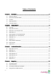
Table of Contents Chapter 1. 1.1 About this manual ............................................................................................................................. 5 1.2 Who should read this manual ........................................................................................................... 5 1.3 Contents ............................................................................................................................................ 5 1.4 Eddy Documents .........
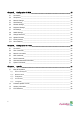
Chapter 5. 5.1 Connection ...................................................................................................................................... 35 5.2 Setup Menu ..................................................................................................................................... 36 5.3 Network Settings ............................................................................................................................. 38 5.4 Serial Settings....................
Eddy User's Guide Chapter 1. Introduction Eddy, SystemBase Embedded Device Server Module, is an optimized minimal CPU module for developing an industrial embedded device. This manual introduces general factions for the Eddy. 1.1 About this manual This manual guides that users are able to develop Eddy for a device server including the function that transfers from serial data to LAN.
Eddy User's Guide 1.4 Eddy Documents The following table summarizes documents included in the Eddy document set.
Eddy User's Guide 1.5 Technical Support You can reach our tech support by following 3 ways; 1. Visit the Eddy official community site at http://www.embeddedmodule.com and go to ‘Technical Support’ menu. FAQ and questions can be reviewed and submitted. 2. E-mail our technical support team to tech@sysbas.com. Any kind of inquiries, requests, and comments are welcomed. 3. Call us at our customer center at 82-2-855-0501 for immediate support.
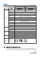
Eddy User's Guide Chapter 2. Getting Started Welcome to Eddy! This chapter includes Eddy series overview, main and distinctive features, package contents for each product, and application fields. 2.1 Overview There are two categories in Eddy; Eddy-CPU module, Eddy Development Kit (DK). Eddy-CPU modules include category of socket type Eddy-CPU and Mini PCI type Eddy-S4M. Eddy-DK includes DK board for Eddy-CPU exclusive, JIG and DK board for Eddy-S4M exclusive.
Eddy User's Guide Type Feature Eddy-CPU v 2.1 CPU AT91SAM9260B-CJ (210 MHz) Memory 8MB Data Flash, 32 MB SDRAM 19 Bit / 16 Bit Data Bus Ethernet I/F 10/100 Base-T Auto MDI/MDIX USB 2.0 FS ADC TWI(I2C) SPI 4 Port, Support up to 921.6 Kbps (1 : Full Signal, 2,3,4, : RxD, TxD, RTS, CTS only) 2 Host /1 Device Port, 2.
Eddy User's Guide guidelines. Please refer to Eddy DK Manual included in the Development Kit for detailed information on the DK.
Eddy User's Guide Feature Type NAND Flash 256MB, 8bit I/F SD Card Connector Push Type, Up to 16 GB MMC / SD Card / MC supported 1 x Device 2 x HOST, Dual-Port USB Connector LCD Module 128 x 64 Dots Matrix Structure KEY Battery Holder LED 4 x 4 Matrix 3V Lithium Battery, 235 mAh Power, Ready, 20 Programmable IO, Console & Serial TxD, RxD I2C Interface 16bit I2C BUS GPIO SPI Interface 2Kbit EEPROM MCI Interface SD Card, MMC Socket ADC Interface Temp / Light Sensor Digital I/O 8 Port Input,
Eddy User's Guide Classification CPU Battery Holder ADC Specification ARM9260B-CJ (210 MHz) AT45DB642D, 8MB Data Flash IS42S16160B, 32 MB SDRAM 10/100 Base-T MAC KSZ8041NLi PHYceiver Auto MDI/MDIX Port 0,1 : RS232 (DB9 male) Port 0 : Full Signal Port 1 : TxD, RxD, RTS, CTS only Port 2,3 : COMBO (Terminal Block 5pin) * COMBO : RS422/RS485 is S/W selectable 3 Host /1 Device Port, 2.
Eddy User's Guide Classification characteristics Environment Specification Dimensions 59.75 x 61.80 x 4 mm Weight Operating Temp Storage Temp Humidity 15 g -40 ~ 85°C -66 ~ 150°C 5 ~ 95% Non-Condensing CE Class A, FCC Class A, RoHS compliant 2.5 Eddy-S4M-DK v2.1 (Development Kit) Eddy-S4M DK is Development Kit supporting programmer can easily materialize and test their application. DK includes Test Board, various connectors, programming environment and document.
Eddy User's Guide Classification ADC Interface Light Sensor USB Connector LAN Port Console Port 1 x Device, 2 x HOST, Dual-Port RJ45 with transformer DB9 Male Power ON/Off switch Serial RS422/485 Termination resistor configuration switch GPIO input test switch(Off : Low, ON : High) RDY, Power, 34 Programmable IO, Console & Serial TxD, RxD LED Used for downloading code and single-stepping through programs Factory Default & Warm Boot (If pushing over 5sec, operate in Factory default) Switch LED JTAG Port
Eddy User's Guide Classification Expansion Header Input Power Dimensions 2.7 Specification Used to connect most functions of S4M to externalS4M 5 VDC 70 x 105 mm Eddy-WiFi v 2.1 Eddy WiFi joined with Eddy-CPU v2.1/v2.5, Eddy-S4M v2.1 enables various serial devices (secure device, communication device, modem, print data device, industrial measuring instrument) to connect wireless LAN. Eddy-WiFi module supports IEEE 802.11 b/g wireless specification. You can set the wireless network parameters.
Eddy User's Guide Classification Data Rate Power consumption 2.8 Specification 802.11b : 11, 5.5, 2, 1 Mbps 802.11g : 54, 48, 36, 24,18,12,11, 9, 6, 5.5, 2 , 1 Mbps TX : 450mA RX : 300mA Host interface USB2.0 Antenna ANT 2.4Ghz, 2DB RP-SMA Female Antenna Cable RF 100mm SMA B/H Dimension 54 x 25 x 6mm Operating Temp 0 ~ 55°C Humidity 5 ~ 90% Non-Condensing Operating Voltages 3.3V±5% Weight Approvals 10g CE Class A, FCC Class A, RoHS Compliant Eddy-BT v2.1 Linking to Eddy-CPU v2.1/v2.
Eddy User's Guide Classification Operating Temp Supply voltage: 3.3V DC Supply current::10mA 60mA Operating temperature: -30 ~ 80 oC Storage Temp Storage temperature: -40 ~ 85 oC Humidity Humidity : 90% (Non-condensing) Power Working distance Approvals 2.
Eddy User's Guide z z z z z z z z z z z z z z z USB host port (Max 12Mbps USB Full speed) SD Card Interface Max 921.
Eddy User's Guide Chapter 3. Hardware Description This chapter provides Eddy’s hardware information, including block diagram, layout, pin specifications, dimensions and other hardware-related issues. 3.1 Eddy-CPU v2.1/v2.5 Ethernet port is provided as pin headers, and the transformer and RJ-45 connector should be manually implemented by users. (RJ-45 connector with embedded transformer, normally called LAN-Mate or MAG Jack, can be used as a simpler approach. Eddy CPU V2.1/v2.
Eddy User's Guide 3.2 Eddy-DK v2.1 It is Development Kit Providing environment to test and developing. Bellow is simple Instruction on Device, Switch, Pin, LED and so on.
Eddy User's Guide External Device Feature A External Device Feature B 21
Eddy User's Guide Internal Device Feature 22
Eddy User's Guide 3.3 Eddy-S4M v2.1 Mini PCI Type Slot.. When developing main board, user must materialize transformer and RJ-45 connector (or RJ45 in which transformer is included (LAN-Mate or MAC Jack)). Since Driver IC is in Eddy-S4M, Serial port can be integrated easily only by attach connector.
Eddy User's Guide 3.4 Eddy-S4M-DK v2.1 Development Kit provides testing and configuration in environment of Eddy-S4M v2.
Eddy User's Guide 3.5 Eddy-S4M-JIG v2.1 It is test board which used when you test with Eddy-S4M v2.1 3.6 Eddy WiFi v2.1 Linking to Eddy-CPU and Eddy-S4M, Eddy-WiFi module enables to use various types of serial device (Security equipment, telecommunications device, modem, data output devices, industrial instruments etc.) through wireless LAN. Eddy-WiFi module supports IEEE 802.11b/g. For application development, please refer to WiFi.c, the source code for Eddy-WiFi module.
Eddy User's Guide LEFT 26 Description RIGHT Description 1 NA 1 NA 2 NA 2 NA 3 NA 4 NA 5 VCC(3.3V) 6 VCC(3.
Eddy User's Guide 3.7 Eddy BT v2.1 Bluetooth module is composed to connect 4th serial port of Eddy-CPU or Eddy-S4M in TTL method. It is possible to use Eddy-BT as 4th serial port, but it can lose data in case of using HW Flow Control. If you want to use HW Flow Control, please refer to Test_Bluetooth.c in SDK and revitalize HW Flow control of 4th serial port. For the details of Eddy-BT, please refer to “7.
Eddy User's Guide 28 LEFT Description RIGHT Description 1 NA 1 NA 2 NA 2 NA 3 NA 3 NA 4 5 6 VCC(3.3V) Factory Reset UART TXD 4 5 6 NA VCC(3.3V) VCC(3.
Eddy User's Guide Chapter 4. Integration This chapter explains how you can make Eddy to communicate. It deals with LAN and pin header connection guides for Eddy to operate together with the target serial device. Follow these steps to connect Eddy to the device and network. 4.1 Connection Guide 1) WAN/LAN In order to connect Eddy to network, you need to use RJ45 Ethernet port. It supports both 10Mbps and 100Mbps Ethernet connection (auto-sensing).
Eddy User's Guide Second is to use “Detector” application provided in the Utility & Documents CD. This application allows searching for Eddy modules on the network. ◆ The factory default IP address: 192.168.0.223 Eddy’s default IP address is set to 192.168.0.223. In order to connect with this address, you need to change network configurations so that your PC can connect to the IP 192.168.0.223.
Eddy User's Guide ◆ Factory default alias IP address: 10.10.1.1 In case you configure Eddy to use DHCP to obtain an IP address automatically, you might find it hard to know the IP address to connect to. To provide users with an easier way to know the current IP address, Eddy has a fixed alias IP that is always accessible. Use the address below whenever you cannot find out Eddy’s IP address.
Eddy User's Guide If Eddy module is not on the same network as the PC you are working on, use “IP Configure” button to temporarily assign an IP address that you would like to make a Web or Telnet connection to. If you assign a temporary IP address to Eddy, you need to to change the IP address and restart in Web or Telnet. Now you are ready to connect to Eddy! There are three options to configure Eddy. 1) Web You can easily configure Eddy with web interface, accessible from any web browser.
Eddy User's Guide To check memory card’s current disk space information, type in "du -sk /tmp/mmc" or "df /tmp/mmc" commands via telnet. Following example displays status of a memory card with 1GB memory storage capacity. Eddy login: eddy Password: # pwd /tmp # ls ifstate login.pw login.id mmc # du -sk /tmp/mmc 9520 /tmp/mmc # df /tmp/mmc Filesystem /dev/sda1 # thttpd.log wtmp thttpd.pid Size 967.2M Used Available Use% Mounted on 9.3M 957.
Eddy User's Guide Eddy login: eddy Password: # fdisk -l Disk /dev/sda: 1014 MB, 1014497280 bytes 44 heads, 32 sectors/track, 1407 cylinders Units = cylinders of 1408 * 512 = 720896 bytes Device Boot Start End Blocks Id System /dev/sda1 1 1408 990704 6 FAT16 Disk /dev/sdb: 4068 MB, 4068474880 bytes 51 heads, 50 sectors/track, 3116 cylinders Units = cylinders of 2550 * 512 = 1305600 bytes Device Boot Start End Blocks Id System /dev/sdb1 1 3117 3973116 b Win95 FAT32 # ls -al /dev/sd* brw-rw---1 root root 8, 0
Eddy User's Guide Chapter 5. 5.1 Configuration via Web Connection Open your favorite web browser and enter the IP address of Eddy to access Eddy’s web manager. Once you are successfully connected, the following front page will show up. You need to enter appropriate username and password to login. Please note that this username and password is used as authentication method for Telnet as well.
Eddy User's Guide 5.2 Setup Menu If login process is successful, you will see a web manager’s main page, showing summary of your device. On the left, you will see a setup menu, and you can navigate through these options. WiFi Disable View ; Since S4M doesn’t support DIO and LCD, “DIO settings” doesn’t appear on the left menu.
Eddy User's Guide WiFi Enable View Main features of Setup Menu are as follows. 37 Menu Descriptions Summary View a summary of Eddy. Network Settings Configure network connection settings. Wireless Settings Configure Wireless settings. Peripheral Settings Select GPIO or Device mode. Serial Settings Configure detailed operation environment for serial communication. GPIO Settings Configure programmable I/O pins. DIO Settings Configure DIO port.
Eddy User's Guide 5.3 Change Password Change ID and password for both Web and Telnet interface. Update Firmware Update Eddy’s firmware. Factory Default Restore all the factory default settings. Save & Reboot Save the configurations and reboot Eddy. Network Settings Configure general network environment and network management. After changing values, you need to click ‘Submit’ button. Then you will see the same page with modified values.
Eddy User's Guide Main features for WAN Configuration is as follows. Menu Default Descriptions Device Name Eddy Name of the current device Line Type Static IP IP obtaining method for Eddy’s network connection. IP Address 192.168.0.223 Subnet Mask 255.255.255.0 Gateway 192.168.0.254 DNS 168.126.63.1 Current IP address Eddy is assigned to. (When line type is Static IP, manually enter an appropriate IP address. When line type is DHCP, current IP is displayed, but it is not editable.
Eddy User's Guide (Username/ Password) Telnet Service Enable Enable or disable Telnet service. If disabled, you cannot connect to Eddy via Telnet. FTP Service Enable Enable or disable FTP service. If disabled, you cannot connect to Eddy via FTP. Web Service Enable Enable or disable Web service. If disabled, you cannot connect to Eddy via Web. SSH Service Disable Enable or disable Secure Shell service.
Eddy User's Guide You can set the communication and operation environment for the serial port. After changing values, you need to click ‘Submit’ button. Then you will see the same page with modified values. Please note that you have to ‘Save & Reboot’ in order to see these changes in effect. Changes will be discarded if you do not save current settings. Menu Default Descriptions Select the operation protocol, which the serial port would use. Disable Do not use this port.
Eddy User's Guide Menu Default Descriptions Socket number for awaiting connections can be set in ‘Local socket port’ field. Once a UDP packet is received to the socket that waits for the connection, the data is transmitted to the serial port. The data input from the serial port is put into UDP packets, which eventually are sent to the client. Interface Local Socket Port 4001 Port Alias Port1 Port alias name for convenience. 16 Characters at maximum. Baud Rate 9600 bps Set communication speed.
Eddy User's Guide Menu Default Descriptions For example, if the operation mode is set to TCP Server and Alive Check Time is configured to 10, TCP Server will listen for the client’s connection and eventually establish a connection. Since the check time is 10 seconds, the server will wait for 10 seconds until the client connected to it sends any packet. If there is no data for 10 seconds, server will quit the connection and return to the listening state.
Eddy User's Guide Menu Wireless Network 44 Default Disable Wireless Mode Infrastructure Wireless Network Mode 802.11b/g Mixed Description When enabled, Eddy-WiFi is available. •Disable: Eddy-WiFi is not available. •Enable: Eddy-WiFi is available. Set the wireless LAN mode. (Option: Infrastructure, Ad-Hoc) •Infrastructure : Use Eddy-WiFi under the Infrastructure mode. This mode is used for connecting to the wireless AP (Access Point) as a client to connect to other network.
Eddy User's Guide Wireless Network Name(SSID ) Channel None Sets the identification (SSID) of a wireless network to be connected. (Up to 32 bytes) Auto Selects a frequency channel for wireless connection. (Option: Auto, 1 ~ 13) •Auto: Connect a channel specified in AP automatically. In most cases, this setting is used. •Value Specification: Specify a channel to be connected manually. Sets the speed for wireless connection. (Option: Auto, 1, 2, 5.
Eddy User's Guide Authenticati on Mode OPEN Encryption Type NONE Key Index 1 Selects the index of the key to be used from the created keys. (Option: 1, 2, 3 and 4) Key None Selects WEP 64-bit (Enter a Hex Key value directly). (Example: 3132333435) Selects WEP 128-bit (Enter a Hex Key value directly) (Example: 31323334353637383940414243) Password None Password for the TKIP encryption type. (Up to 64 bytes) DHCP Sets an IP address type in a wireless network.
Eddy User's Guide Subnet Mask Gateway DNS 5.6 255.255.255.0 Sets an IP address of a wireless network. If the line Type is Static IP, a user can enter a subnet mask address directly. If line type is DHCP, the current subnet mask address is displayed. In DHCP type, the address cannot be changed. 192.168.1.1 Sets a gateway address of a wireless network. If the line Type is Static IP, a user can enter a gateway address directly. If line type is DHCP, the current gateway address is displayed.
Eddy User's Guide Configuration view of Eddy-CPU 48
Eddy User's Guide Configuration view of Eddy-S4M 5.7 DIO Settings Eddy-DK supports 16 Channel Digital inputs and outputs (DIO) by connecting with I2C interface. It is possible to switch GLCD or Digital IO port via 16 Channel DIO. After changing values, you need to click ‘Submit’ button. Then you will see the same page with modified values. Please note that you have to ‘Save & Reboot’ in order to see these changes in effect. Changes will be discarded if you do not save current settings.
Eddy User's Guide Menu Device Select 5.8 Default Descriptions LCD Set the purpose of the I2C 16 Bit I/O channel. LCD: Set the G-LCD mode. If you set to the LCD, you cannot use it for the DIO port. DIO: Set the DIO 16 channel mode. You can set input or out 16 channel as like the GPIO. If you set to the DIO, you cannot use it for the G-LCD. SNMP Settings You can set the communication and operation environment for the SNMP Agent. After changing values, you need to click ‘Submit’ button.
Eddy User's Guide In order to use the SNMP Agent, SNMP v1/v2/v3 Agent become enabled and pushes the [Submit] button. Feature Default Descriptions Enable or disable Simple Network Management Protocol (SNMP) SNMP v1/v2/v3 Disable support. Agent (Options : Disable/Enable) SNMP V1/2 Attributes can read and write by SNMP Agent. In order to read attributes only, change the feature to "ReadOnly". In order to read and write attributes, change the feature to V1/2 Attribution ReadOnly "ReadWrite".
Eddy User's Guide 5.9 Change Password Change Web/Telnet access username and password. After changing values, you need to click ‘Submit’ button. Then you will see the same page with modified values. Please note that you have to ‘Save & Reboot’ in order to see these changes in effect. Changes will be discarded if you do not save current settings. ◆ Default user id : eddy ◆ Default password : 99999999 5.10 Update Firmware Firmware is an application embedded in Flash memory of Eddy.
Eddy User's Guide 5.11 Factory Default Restore all the configuration parameters to the factory default values. Clicking on ‘Restore Factory Defaults’ button will delete all current settings and restore settings to the initial status. Eddy will automatically reboot. You cannot turn back the decision once you select this option. ◆ The factory default WAN IP Address: 192.168.0.223 ◆ The factory default LAN IP Address: 10.10.1.
Eddy User's Guide 5.12 Save & Reboot This option saves changes to the Flash memory and restarts the system to let the changes to take place in the operation. Main features for Save & Reboot are as follows 54 Menu Descriptions Save and Reboot ‘Save & Reboot’ reboots Eddy after saving changes to Flash memory. Reboot Only ‘Reboot Only’ option just reboots Eddy without saving changes. This option can be used to rollback the changes you have mistakenly made.
Eddy User's Guide Chapter 6. 6.1 Configuration via Telnet Connection Open your telnet client and enter Eddy’s IP address to connect. You need to enter appropriate username and password to login. Please note that this username and password is used as authentication method for Web as well. This means if username or/and password has been modified from the telnet interface, modified values have to be entered to connect to web, and vice versa.
Eddy User's Guide 6.3 def view lan Show LAN network settings. def view wifi Show WiFi network settings. def view management Show managing items settings. def view port Show serial port settings. def view gpio Show GPIO pin settings. def view dio Show DIO pin settings. def help Show command list and help. Network commands Configure general network environment and network management.
Eddy User's Guide def portviewport 4000 Set the socket number of the PC with Portview installed. def telnet [Enable / Disable] Enable Enable or disable Telnet service. If disabled, you cannot connect to Eddy via Telnet. def ftp [Enable / Disable] Enable Enable or disable FTP service. If disabled, you cannot connect to Eddy via FTP. def ssh [Enable / Disable] Disable Enable or disable SSH service. If enabled, you can connect to Eddy via SSH. 203.32.117.
Eddy User's Guide "ReadWrite.” (Options : ReadOnly/ ReadWrite) 6.4 def v3username [string] eddy Configure the Username when use SNMP V3. def v3password [string] none Configure the password when use SNMP V3. def trapip [address] 0.0.0.0 Configure the server IP address which receives the TRAP information. def trapoprt [Socket No.] 162 Configure the server Port which receives the TRAP information. def trap_reset [enable, disable] Enable If Enable is selected, inform the "System reset info".
Eddy User's Guide def wifi network <802.11 b/g mixed, 802.11b only, 802,11g only, 802.11 b/g mixed Configure the active protocol of wireless network. def wifi ssid None Configure wireless network name (SSID) you want connect. def wifi channel Auto Configure the speed of wireless connection.
Eddy User's Guide 6.5 Serial Commands You can set the communication and operation environment for the serial port. Chapter 5 describes each option in detail. Only a summary of each option is presented here. Commands Default Descriptions def port 1 protocol [disable / com/ tcp_server/tcp_client/ tcp_broadcast / tcp_multiplex/ udp_server/udp_client] com Select the operation protocol, which the serial port would use.
Eddy User's Guide Commands def port 1 login [Enable / Disable] def port 1 loginname def port 1 loginpass 6.6 Default Disable None None Descriptions When the Operation Mode is set to TCP Server, ask for the username and password when the client tries to connect. Set to 1 to enable.
Eddy User's Guide Chapter 7. apendix 7.1 Eddy-BT Operation 7.1.1 How to use Eddy-BT Eddy-BT is an optional module that can be loaded and used with Eddy-CPU module. The communication interface of Eddy-BT is RS-232 and connected with 4th serial port of Eddy-CPU module. If you want to develop your own application using Eddy-BT, please refer to “Test_BlueTooth.c” in “FileSystem” source. Also, you can use the default applications (Com_Redirect, TCP_Server) without additional development.
Eddy User's Guide 1. 2. 3. 4. 5. 6. 7. 7.1.2 Please power on Eddy-DK after you connect Eddy-BT with Eddy-CPU module. Please set the “Operation Mode” of 4th serial port as “Com_Redirector” mode. And then, press “Save” button. Please press “Save & Reboot” button of “Save & Reboot” menu. And then, Eddy-DK will be rebooted. Please install COM_Redirector program on PC. (For more information, please refer to the manual of Com_Redirector program.
Eddy User's Guide address, which is composed of 12 hexa-decimal numbers. Eddy-BT has 4 operation modes as follows: Mode Description Mode0 In this mode, there is no response when power on or software reset, and Eddy-BT is just waiting for AT command input. Neither master nor slave is assigned to Eddy-BT in mode0. User can change the configuration parameters of Eddy-BT in this mode. Eddy-BT must be in Mode0, when it is directly controlled by AT commands. The factory default is set to Mode0.
Eddy User's Guide Data Bit Eddy-BT supports only 8 data bit. In the case of 7 data bit and even/odd parity, use Eddy-BT 8 data bit and none parity. At this time, master and slave are Eddy-BT. But 7 data bit and none parity is not support. Hardware Flow Control) Eddy-BT plugged into its host system transmits data from host to the other side Bluetooth device. This data is saved temporarily in the internal buffer of Eddy-BT and sent repeatedly until the transmission is completed packet by packet.
Eddy User's Guide +++ OK ATD000195000004 CONNECT000195000004 +++ AT+BTMODE,1 After rebooted automatically master tries to connect to slaves After input the BD addresses of the slave units into 4 S-registers S46, S54, S55 and S56 and then set operation mode as MODE1, users can use multiple connection function. If S-registers have available slaves’ address, AUTO CONNECT message will be displayed following corresponding TASK.
Eddy User's Guide ATOx, ATObdaddr Using the ATO command, the communication status with the last active slave or a specific slave can be set to online (only in Node Switching Mode). 7.1.4 ATO Communicate with the slave recently communicated. ATOx (ATO1, ATO2, ATO3, ATO4) Communicate with the slave which belongs to the TASK x. ATObdaddr (ATO000195000001) Communicate with the slave with specified BDaddress. AT Command AT command AT command set is a in fact standard language for controlling modems .
Eddy User's Guide Symbols The symbols are used for the description of command syntax as follows: Symbols Meaning ASCII Code Carriage return 0x0D Line feed 0x0A Carriage return + Line feed 112233445566 Bluetooth device address N or m One digit decimal number to Timeout in seconds Command Category Command Category AT Commands RESET 1 2 ATZ AT&F SERIAL PORT 3 4 AT AT+UARTCONFIG,b,p,s,h Information 5 6 7 8 9 10 AT+BTINFO? AT+BTINQ? AT+BTLAST? AT+BTVER? AT+BTRSSI,n AT+MLIST? Mode
Eddy User's Guide Security 25 26 27 28 29 AT+BTKEY=$string AT+BTSD? AT+BTCSD AT+BTFP,n AT+BTSEC,a,e Miscellaneous 30 31 AT+BTNAME=$string AT+BTLPM,n 32 33 34 AT&V ATSnn? ATSnn=mm S-REGISTER ATZ Response OK Purpose Software Reset Description This has the same effects as Powercycling the unit. This command disconnects any connected Bluetooth device, and stops ongoing tasks. After rebooting, the status will be decided by the preset operation mode.
Eddy User's Guide AT+UARTCONFIG,Baudrate,Parity,Stopbit,Hwfc Response OK Purpose Set Serial parameters Parameter s Baudrate=1200/2400/4800/9600/14400/19200/38400/57600/115200/230400/460800/9 21600 (Default=9600) Parity=N/E/O (Default=N) Stopbit=1/2 (Default=1) Hwfc(Hardware Flow Control)=0/1 (Default=1) Descriptio n The Serial parameters can be set or changed. The factory default is 9600, N, 1, 1. To take effect the ATZ command must be used or Powercycle the unit.
Eddy User's Guide AT+BTLAST? Response 112233445566 Purpose Display the BD address of the last connected device Description The Bluetooth device last connected to this Eddy-BT is displayed with its BD address. AT+BTVER? Response ESD100V2_v2.0.
Eddy User's Guide TASK3 TASK4 DISCONNECT 000195000004 AT+BTMODE,n Response OK Purpose Set operation mode Parameters n=0: MODE0 (Default) n=1: MODE1 n=2: MODE2 n=3: MODE3 Description When the operation status is ‘Pending’ currently, change the status to ‘Standby’ with AT+BTCANCEL prior to this command.
Eddy User's Guide AT+SETESC,nn Response OK Purpose Change the escape sequence character Description Escape sequence character set to ‘+’ by default is changeable. The parameter nn must be a printable character. Example AT+SETESC,42 ATO (ATOx, ATObdaddr) Response None Purpose Convert the operation status of ‘Standby’ to ‘Connect’ Description You can convert the operation status of ‘Standby’ to ‘Connect’ ready to transmit data.
Eddy User's Guide AT+BTSCAN,n,to Response OK CONNECT 112233445566 or OK ERROR Purpose Wait for inquiry and connection from other Bluetooth devices for a given duration Parameters n=1: Allows Inquiry scan n=2: Allows Page scan n=3: Allows both of Inquiry scan and Page scan to= Time duration in seconds Description For the given to, Eddy-BT is waiting for the inquiry and connection from other Bluetooth devices. If the parameter of to is 0, it will wait forever.
Eddy User's Guide Purpose Connect to the last connected Bluetooth device Description Eddy-BT saves the BD address of the Bluetooth device most recently connected to. If it fails to make a connection, response will display an ‘ERROR’. ATD112233445566 Response OK CONNECT 112233445566 or OK ERROR Purpose Connect to a specific Bluetooth device with a given BD address Parameters 112233445566=BD address Description Eddy-BT attempts to connect to the Bluetooth device with the given BD address.
Eddy User's Guide TH (ATHx, ATHbdaddr) Response OK DISCONNECT Purpose Release the current connection Description The current Bluetooth connection will be disconnected. It takes about Supervision Timeout(S37) to detect an abnormal disconnection such as power off and moving out of service range. In multiple connection modes, a specific connection can be specified to be disconnected by specifying the connection number or the Bluetooth address.
Eddy User's Guide AT+BTFP,n Response OK Purpose Set generation of link key every time of connection Parameters n=0: Inactivate (Default) n=1: Activate Description If n is set to 1, Eddy-BT asks for the pin code every time a connection is made. This can be used to increase security.
Eddy User's Guide AT&V Response S0:m0;S1:m1; …Sn:mn OK Purpose Display all the S-registers Description All parameters are stored at S-register in flash memory. These values are sustained until hardware reset. Response S0:m0;S1:m1; …Sn:mn OK ATSnn? Response value OK Purpose Display a given S-register Parameters nn= Address of S-register Description A specific S-register will be displayed.
Eddy User's Guide ATA112233445566 ◎ ATA ◎ AT+BTSCAN ◎ AT+BTSCAN,n,to ◎ AT+BTSCAN112233445566,to ◎ AT+BTCANCEL ○ +++ ○ AT+SETESC ◎ ATO ● ATH ● AT+BTSEC,Auth,Encr ◎ AT+BTLAST? ○ AT+BTMODEn ◎ AT+BTNAME=”Name” ◎ AT+BTKEY=”nnnn” ◎ AT+BTINFO? ○ AT+BTLPM,n ◎ AT+BTSD? ○ AT+BTCSD ◎ AT+BTFP,n ◎ AT+UARTCONFIG,b,p,s,h ◎ AT+BTVER? ○ AT+BTRSSI,n ● ○ ○ ○ ◎ Valid only when Eddy-BT is not connected to other Bluetooth device.
Eddy User's Guide S1: Force to Reconnect (default 1) S1=0, Eddy-BT in Mode1 does not try to reconnect when disconnected. S1=1, Eddy-BT in Mode1 keeps trying to reconnect when disconnected. S3: Stream UART Policy (default 0) S3=0, the priority of UART streaming is throughput. S3=1, the priority is latency, which minimizes the delay of data transmission. This is useful in case of transmitting very small data quickly.
Eddy User's Guide to Standby. Since the Eddy-BT skips the process of detecting escape sequence characters, more efficient data transmission can be had. S11=1, Eddy-BT allows for the escape sequence character. Whenever it is needed, the Connect status can be changed to Standby. S12: Clear Data Buffer When Disconnected (default 0) S12=0, Eddy-BT does not clear the data buffer received from host system when disconnected. S12=1, Eddy-BT clears the data buffer when disconnected.
Eddy User's Guide S26: Intercharacter Timeout (default 0) This value describes time interval between characters used to separate the data from serial port. If there is no more data coming from serial port in this value, data is sent to client.
Eddy User's Guide of 0. In case of 3E0100, bluetooth devices with COD 3E0100 are inquired. S45: Inquiry Access Code (default 0x9E8B33) Inquiry access code is used during inquiry state. The reserved IAC addresses are 0x9E8B00 ~ 0x9E8B3F. The general inquiry IAC is 0x9E8B33. Eddy-BT is able to find the Bluetooth devices that are configured as the same IAC. S46: BD Address of Last Connected Device This saves the BD address of the Bluetooth device connected most recently in single connection mode.
Eddy User's Guide S58: MAX TX POWER (default 0) This value describes the peak output power. Setting this causes rebooting and applying. (There is a little deviation according to the devices.) Parameter 0 1 2 3 4 5 6 7 8 84 dBm Use chip setting.
Eddy User's Guide 7.2 Firmware Updates via FTP Eddy supports firmware update with Web or FTP. This section describes update method via FTP and Telnet. Web update is described in Chapter 5. Configuration via Web. 1) 2) 3) 4) Connect to Eddy with FTP, using correct username and password. (Default: eddy, 99999999) Issue a command ‘bin’ for binary file transfer mode. Optionally use ‘hash’ to see the data transfer mark. Issue ‘put’ command upload the firmware file.
Eddy User's Guide 86
Eddy User's Guide 7.3 Ordering Information Product 87 Version Descriptions Eddy-CPU 2.1 Embedded CPU Module Eddy-CPU 2.5 Embedded CPU Module Eddy-DK 2.1 Eddy V2.1 Development Kit Eddy-S4M 2.1 Embedded CPU Module (Mini PCI Type) Eddy-S4M-DK 2.1 Eddy-S4M v2.1 Development Kit Eddy-S4M-JIG 2.1 Eddy-S4M v2.1 JIG Board Eddy-WiFi Eddy-BT 2.1 2.1 802.
Eddy User's Guide 7.4 FCC Statement THIS DEVICE COMPLIES WITH PART 15 OF THE FCC FULES. OPERATION IS SUBJECT TO THE FOLLOWING TWO CONDITIONS: 1) THIS DEVICE MAY NOT CAUSE HARMFUL INTERFERENCE. 2) THIS DEVICE MUST ACCEPT ANY INTERFERENCE RECEIVED. 3) INCLUDING INTERFERENCE THAT MAY CAUSE UNDESIRED OPERATION. FCC RF INTERFERENCE STATEMENT NOTE: This equipment has been tested and found to comply with the limits for a Class A digital device, pursuant to part 15 of the FCC Rules.