
Instruction Manual


UM0039_Ai-LB 5k_EN_V01_0223 26
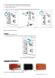
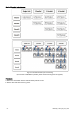
Fig. 5.4.3 Dial Diagram Setting Process
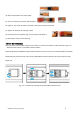
5.5 Turn On the System
1. Arrange the communication/power cable properly.
2. Ensure that all conduit or cable gland junctions are properly dealed.
3. Switch on button to “ON” side on each LB51100A inside .
4.Turn on the circuit breaker to “ON” side.
5.When battery establishes communication with the Inverter,the inverter can read the battery information.
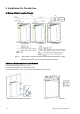
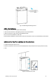
5.6 Reinstall the Front Panel and Close the Protective Cover.
1. Install the front panel refer to 5.6.1.
2.Close the protective cover of the circuit breaker(Reverse the procedure for the open protective cover).
3. End.
Fig.5.6.1 Install the front panel