
Instruction Manual


UM0039_Ai-LB 5k_EN_V01_0223 22
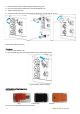
(3) Swipe outer isolation layer of DC cable.
(4) The red is used for the positive, and the black is
for negative , The end of the cable is bunched at the terminal using a wire clamp.
(5) Tighten the isolation cap and plug contact.
(6) Put the positive and negative plug on to the system and tighten it.
(7) Use isolation cap for unused DC plug.
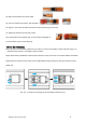
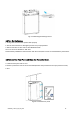
4.4 Turn On the System
Step1. Open the circuit breaker protective cover and turn on the circuit breaker to “ON” side refer to Fig. 4.4.1
(Ensure that the inverter is connected to the PV module)
Step2. When battery establishes communication with the Inverter, the inverter can read the battery information.
Step3.Close the protective cover of the circuit breaker.(Reverse the procedure for the open protective cover).
Step4. End.
Fig. 4.4.1 Procedure for opening the circuit breaker protective cover