
Instruction Manual


UM0039_Ai-LB 5k_EN_V01_0223 20
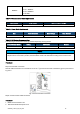
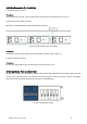
RS485x2
Pin 1, 4, 5: NC
Pin 2, 7: RS485-A
Pin 3, 6: RS485-B
Pin 8: GND
Table 4-3 Communication Cable Requirements
Cable Gauge
Strip Length
Maximum Cable Length
CAT5 or better (24 AWG)
RJ-45 connector
45 m
Table 4-4 Power Cable Requirements
Size
Outer Diameter
Max. Voltage
Max. Current
21-33 mm²
10-12 mm
1000 V
120 A
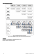
Table 4-5 DC Breaker Recommendation
The following circuit breaker models (purchased separately) are supported:
Circuit Breaker Model
Rating
Certificate
Remark
Nader NDB1-125
100 A
CCC, CE, CB, TUV, UL1077
For single set use
NOTE
A DC Breaker is required for each positive and negative terminal connecting,when
multiple sets are connected in parallel, the DC Breaker needs to be selected according to the actual current.
Procedure:
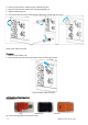
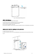
Step1.Ground cable connection
Ground cable connection:use a screwdriver to fix the ⑧ground wire terminal to the battery ground point refer to
Fig. 4.3.3.
Fig. 4.3.3 Ground cable connection
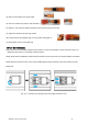
Step2. Communication cable connection
Procedure:
1. Make sure the breaker is off.
2. Take off the RJ45 waterproof cover.