
Instruction Manual

19 UM0039_Ai-LB 5k_EN_V01_0223
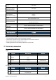
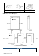
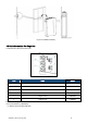
Fig. 4.3.1 Front Panel Interface
Table 4-1 Interface Definition
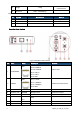
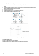
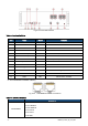
(2)Port CAN/RS485 and RS485 of Battery
Fig. 4.3.2 CAN/RS485 and RS485 connections
Table 4-2 RJ45 Port Definition
Description
CAN/RS485x1
Pin 1: NA
Pin 2,7: RS485-A
Pin 3,6: RS485-B
Pin 4: CAN-H
Pin 5: CAN-L
Pin 8: GND
Item
Name
Model
Remarks
1
SOC LED x4
2
Alarm LED
3
RUN LED
4
Dialer
5
Communication port
RJ45
CAN To PCS, RS485 Internal Connection
6
Communication port *2
RJ45
RS485 Internal Connection
7
Reset
Wake up the system from malfunction status
8
Dry Contact
9
Power On/Off Switch
10
Port Negative x2
PSR6XAB
Black 5.7, 25 mm2
11
Port Positive x2
PSR6XBB
Orange 5.7, 25mm2
12
WIFI
13
GND
M6
Yellow-Green, 10 AWG