
User Manual


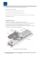
Table Of Contents
- Section1 Safety & Certification Notice
- Section2 System configuration and Functions
- 2.1 HROU (High power Remote Optic Unit)
- 2.1.1 Specifications of HROU
- 2.1.2 Block Diagram of HROU
- 2.1.2.1 HMRU block diagram
- 2.1.2.2 HROU inner look
- 2.1.2.3 HROU part list
- 2.1.3 Function by unit
- 2.1.3.1 High Remote Drive Unit (HRDU)
- 2.1.3.2 Remote Power Supply Unit ( RPSU)
- 2.1.3.3 Remote Optic(ROPTIC)
- 2.1.3.4 Remote Central Processor Unit (RCPU)
- 2.1.3.5 Multiplexer
- 2.1.3.6 System interface unit (SIU)
- 2.1.4 Bottom of HROU
- 2.1.4.1 Functions
- 2.1 HROU (High power Remote Optic Unit)
- Section3 System Installation

Confidential & Proprietary 31/44
Figure 17. Procedures of installation
3.1.4 HROU components
HROU has the following components:
No. Unit Description Remark
Common
Part
Enclosure Including Wall mounting bracket 1EA
RCPU - 1EA
R_OPTIC With SC/ACP adaptor(only HMRU) 1EA,optional
RPSU AC 110/220V or DC -48V 1EA
FAN UNIT 2 FANs is inside 1EA
CU1-
L7085IC19P21A
Multiplexer1
This integrated combiner unit combines all bands
for output to a single antenna connection.
1EA
CU2-
L7085IC19P21A
Multiplexer2
This integrated combiner unit combines all low
bands (<1 GHz) to one antenna connection and all
high bands (>1 GHz) to a second antenna
connection.
1EA