
User Manual

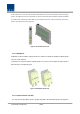


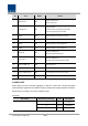


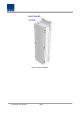
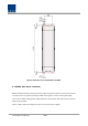
Table Of Contents
- Section1 Safety & Certification Notice
- Section2 System configuration and Functions
- 2.1 HROU (High power Remote Optic Unit)
- 2.1.1 Specifications of HROU
- 2.1.2 Block Diagram of HROU
- 2.1.2.1 HMRU block diagram
- 2.1.2.2 HROU inner look
- 2.1.2.3 HROU part list
- 2.1.3 Function by unit
- 2.1.3.1 High Remote Drive Unit (HRDU)
- 2.1.3.2 Remote Power Supply Unit ( RPSU)
- 2.1.3.3 Remote Optic(ROPTIC)
- 2.1.3.4 Remote Central Processor Unit (RCPU)
- 2.1.3.5 Multiplexer
- 2.1.3.6 System interface unit (SIU)
- 2.1.4 Bottom of HROU
- 2.1.4.1 Functions
- 2.1 HROU (High power Remote Optic Unit)
- Section3 System Installation

Confidential & Proprietary 25/44
No Port HMRU Remark
1 Optical Port 1EA
SC/APC, Waterproof
Optiacl Input port
2 T/RX RF Port 2EA
N Type-Female
Connected for transmittering TX to ARU
and recieving RX signal from ARU.
3 ANT1 1EA DIN-type female_CU option1 ,2 and 3
4 ANT2 1EA DIN-type female_CU option2 and 3
5 ANT3 1EA DIN-type female_Only CU Option3
6 ANT4 1EA DIN-type female_Only CU Option3
7 Power IN 1EA
MS-Con, Waterproof
AC Power IN Or DC Power IN
8 Power OUT 1EA
MS-Con, Waterproof
AC 120V Output port(Only AC) to ARU
9 External FAN unit 1EA Waterproof-Con
10 GND LUG PORT 1EA Terminal for system ground
11 External ALM In/Out 1EA Input/output terminal for dry contact
12 I/O Port 1EA Port for communicate with ARU
POWER PORT
Power ports are used for power-supplying of -48V DC or 120V AC, and specific power
cable should be applied to each different types of ROU power supply (AC/DC or DC/DC).
Below figure is naming of the power supply by type.
AC Power
Port outlook MS Connector numbering Name Description
A AC_H AC Hot
B AC_N AC Neutral
C N.C Not Connected