
User Manual

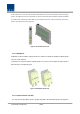


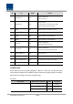


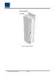
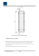
Table Of Contents
- Section1 Safety & Certification Notice
- Section2 System configuration and Functions
- 2.1 HROU (High power Remote Optic Unit)
- 2.1.1 Specifications of HROU
- 2.1.2 Block Diagram of HROU
- 2.1.2.1 HMRU block diagram
- 2.1.2.2 HROU inner look
- 2.1.2.3 HROU part list
- 2.1.3 Function by unit
- 2.1.3.1 High Remote Drive Unit (HRDU)
- 2.1.3.2 Remote Power Supply Unit ( RPSU)
- 2.1.3.3 Remote Optic(ROPTIC)
- 2.1.3.4 Remote Central Processor Unit (RCPU)
- 2.1.3.5 Multiplexer
- 2.1.3.6 System interface unit (SIU)
- 2.1.4 Bottom of HROU
- 2.1.4.1 Functions
- 2.1 HROU (High power Remote Optic Unit)
- Section3 System Installation

Confidential & Proprietary 23/44
each module. Each unit need to connected to the correct slot of the SIU.
Figure 11. SIU Outer Look
2.1.4 Bottom of HROU
2.1.4.1
Functions
The Bottom look of HROU depends on the combine unit(CU) with 3 options.
The CU option1 and 2 need to install a specified CU in the enclosure like the table below explains.
Thus, the CU option1 has one antenna port, the CU option2 has two antenna ports.
Finally, the CU option3 with 4 antenna ports is not necessary to install CU in the enclosure and needs to
apply the panel with 4-DIN Type on the bottom of HROU.
See table and drawing below for.