
Installation and Operation Manual

Confidential & Proprietary 5/57 Alliance-TR
List of Illustrations
Figure 2.1 – HROU System Topology .......................................................................................... 11
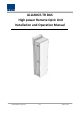
Figure 4.1 – High power Remote Optic Unit (HROU) .................................................................. 14
Figure 4.2 – HMRU Block Diagram .............................................................................................. 15
Figure 4.3 – HARU Block Diagram ............................................................................................... 16
Figure 4.4 – HROU Inside View ................................................................................................... 17
Figure 4.5 – High power Remote Drive Unit (HRDU) .................................................................. 19
Figure 4.6 – Remote Power Supply Unit ..................................................................................... 25
Figure 4.7 – R-Optic Module ....................................................................................................... 26
Figure 4.8 – Remote Central Processing Unit ............................................................................. 26
Figure 4.10 – HROU Bottom Panel ............................................................................................. 27
Figure 5.1 – High power Remote Optic Unit (HROU) .................................................................. 30
Figure 5.2 –HROU Dimensions (Wall Mounting (mm)) ............................................................... 31
Figure 5.3 – HROU Wall Mount Procedure ................................................................................. 32
Figure 5.4 – Connecting HMRU with HARU ................................................................................ 35
Figure 5.5 – Ground Terminal ..................................................................................................... 37
Figure 5.6 – Ground Terminal ..................................................................................................... 37
Figure 5.7 – Ground Terminal Installation .................................................................................. 38
Figure 5.9 – HRDU Configuration ................................................................................................ 39
Figure 5.10 – Guide Rail .............................................................................................................. 40
Figure 5.11 – HRDU Installed ...................................................................................................... 41
Figure 5.12 – Installing Blank Card ............................................................................................. 41
Figure 6.1 – Level Diagram ......................................................................................................... 43
Figure 6.2 – Detailed Information on HRDU ............................................................................... 44