
User's Manual

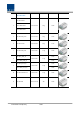


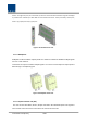

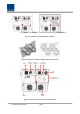

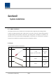
Table Of Contents
- Section1 Safety & Certification Notice
- Section2 System configuration and Functions
- 2.1 HROU (High power Remote Optic Unit)
- 2.1.1 Specifications of HROU
- 2.1.2 Block Diagram of HROU
- 2.1.2.1 HMRU block diagram
- 2.1.2.2 ROU inner look
- 2.1.2.3 HROU part list
- 2.1.3 Function by unit
- 2.1.3.1 High Remote Drive Unit (HRDU)
- 2.1.3.2 Remote Power Supply Unit ( RPSU)
- 2.1.3.3 Remote Optic(ROPTIC)
- 2.1.3.4 Remote Central Processor Unit (RCPU)
- 2.1.3.5 Multiplexer
- 2.1.3.6 System interface unit (SIU)
- 2.1.4 Bottom of HROU
- 2.1.4.1 Functions
- 2.1 HROU (High power Remote Optic Unit)
- Section3 System Installation

Confidential & Proprietary 26/47
Figure 11. SIU Outer Look
2.1.4 Bottom of HROU
2.1.4.1
Functions
The Bottom look of HROU depends on the combine unit(CU) with 3 options.
The CU option1 and 2 need to install a specified CU in the enclosure like the table below explains.
Thus, the CU option1 has one antenna port, the CU option2 has two antenna ports.
Finally, the CU option3 with 4 antenna ports is not necessary to install CU in the enclosure and needs to
apply the panel with 4-DIN Type on the bottom of HROU.
See table and drawing below for.