
User's Manual

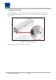

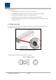
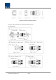
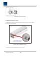
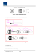
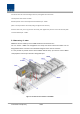
Table Of Contents
- Section1 Safety & Certification Notice
- Section2 System configuration and Functions
- 2.1 HROU (High power Remote Optic Unit)
- 2.1.1 Specifications of HROU
- 2.1.2 Block Diagram of HROU
- 2.1.2.1 HMRU block diagram
- 2.1.2.2 HROU inner look
- 2.1.2.3 HROU part list
- 2.1.3 Function by unit
- 2.1.3.1 High Remote Drive Unit (HRDU)
- 2.1.3.2 Remote Power Supply Unit ( RPSU)
- 2.1.3.3 Remote Optic(ROPTIC)
- 2.1.3.4 Remote Central Processor Unit (RCPU)
- 2.1.3.5 Multiplexer
- 2.1.3.6 System interface unit (SIU)
- 2.1.4 Bottom of HROU
- 2.1.4.1 Functions
- 2.1 HROU (High power Remote Optic Unit)
- Section3 System Installation

Confidential & Proprietary 36/44
The procedures are
1. Loosen a two M6 screws and then take compression terminal off
2. Insert AWG#6 Grounding Wire into terminal and then compress a terminal using tool
3. Assemble the terminal which made in step “2” using 2xM6 screws
4. Cut the ground wire to proper length and connect it to the earth ground source
( Round terminals located on the side of a 1 mm2 (16 AWG) or more wires Using permanently
connected to earth.)
3.1.7 HROU Optical Cable
The Optical Connector is located at the bottom of Remote Unit enclosure fixed. Optical Cable can be
connected by using connectors.
Figure 21. Location of Optical Connector
The specification of compression Optic Connector is like below.