
User's Manual
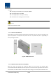
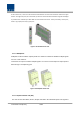
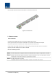
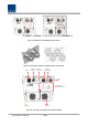
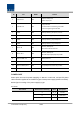
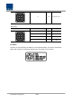
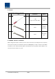
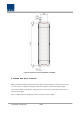
Table Of Contents
- Section1 Safety & Certification Notice
- Section2 System configuration and Functions
- 2.1 HROU (High power Remote Optic Unit)
- 2.1.1 Specifications of HROU
- 2.1.2 Block Diagram of HROU
- 2.1.2.1 HMRU block diagram
- 2.1.2.2 HROU inner look
- 2.1.2.3 HROU part list
- 2.1.3 Function by unit
- 2.1.3.1 High Remote Drive Unit (HRDU)
- 2.1.3.2 Remote Power Supply Unit ( RPSU)
- 2.1.3.3 Remote Optic(ROPTIC)
- 2.1.3.4 Remote Central Processor Unit (RCPU)
- 2.1.3.5 Multiplexer
- 2.1.3.6 System interface unit (SIU)
- 2.1.4 Bottom of HROU
- 2.1.4.1 Functions
- 2.1 HROU (High power Remote Optic Unit)
- Section3 System Installation

Confidential & Proprietary 22/44
At the same front, it also has communication LED Indicators to show communication status with upper
devices. Through Local port, the unit enables you to check and control device status through PC and laptop.
It provides three interface port with ARUs to communicate with these. It also provide dry contact port,
which is (1) output port and (1) input port.
Figure 9. AC-DC RPSU Outer Look
2.1.3.5 Multiplexer
Multiplexer it called combine unit(CU) works as a module to combine or distribute multiple signals
into one or two antennas.
This device has a port to combine multiple signals. You need to connect input and output ports of
RDU through a corresponding port.
Figure 10. Multiplexer Outer Look
2.1.3.6 System interface unit (SIU)
This unit connect with HRDU, R CPU, R Optic and RPSU. SIU distributes power and signals to