
User's Manual
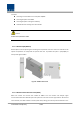
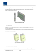
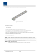
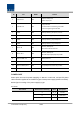
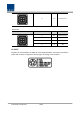
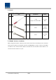
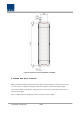
Table Of Contents
- Section1 Safety & Certification Notice
- Section2 System configuration and Functions
- 2.1 HROU (High power Remote Optic Unit)
- 2.1.1 Specifications of HROU
- 2.1.2 Block Diagram of HROU
- 2.1.2.1 HMRU block diagram
- 2.1.2.2 HROU inner look
- 2.1.2.3 HROU part list
- 2.1.3 Function by unit
- 2.1.3.1 High Remote Drive Unit (HRDU)
- 2.1.3.2 Remote Power Supply Unit ( RPSU)
- 2.1.3.3 Remote Optic(ROPTIC)
- 2.1.3.4 Remote Central Processor Unit (RCPU)
- 2.1.3.5 Multiplexer
- 2.1.3.6 System interface unit (SIU)
- 2.1.4 Bottom of HROU
- 2.1.4.1 Functions
- 2.1 HROU (High power Remote Optic Unit)
- Section3 System Installation

Confidential & Proprietary 21/44
Functions:
Providing a circuit breaker to turn AC power ON/OFF
Providing DC power each HRDU
Providing DC power and signal to FAN tray
LED indicators for showing alarm staus of PSU
Caution
DOUBLE POLE/NEUTRAL FUSING
2.1.3.3 Remote Optic(ROPTIC)
Remote Optic converts optical signals into RF signals and performs vice versa. It also has internal ATT for
optical compensation to compensate for optical cable loss. It provides two path in pairs(TX/RX) to
transport RF signal to ARUs.
Figure 8. R OPTIC Outer Look
2.1.3.4 Remote Central Processor Unit (RCPU)
RCPU can monitor and control each module of HROU. This unit receives and analyzes upper
communication data from Remote Optic and reports the unit's own value to upper devices. At the front
of the module, it has LED indicator to show system status, letting you check any abnormalities at a time.