
User's Manual
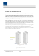
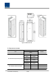
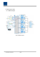
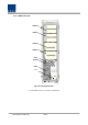
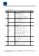
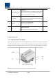
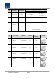
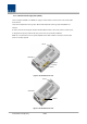
Table Of Contents
- Section1 Safety & Certification Notice
- Section2 System configuration and Functions
- 2.1 HROU (High power Remote Optic Unit)
- 2.1.1 Specifications of HROU
- 2.1.2 Block Diagram of HROU
- 2.1.2.1 HMRU block diagram
- 2.1.2.2 HROU inner look
- 2.1.2.3 HROU part list
- 2.1.3 Function by unit
- 2.1.3.1 High Remote Drive Unit (HRDU)
- 2.1.3.2 Remote Power Supply Unit ( RPSU)
- 2.1.3.3 Remote Optic(ROPTIC)
- 2.1.3.4 Remote Central Processor Unit (RCPU)
- 2.1.3.5 Multiplexer
- 2.1.3.6 System interface unit (SIU)
- 2.1.4 Bottom of HROU
- 2.1.4.1 Functions
- 2.1 HROU (High power Remote Optic Unit)
- Section3 System Installation

Confidential & Proprietary 17/44
CU2-L7085IC19P21A
Multiplexer2
This integrated combiner unit combines all low bands (<1
GHz) to one antenna connection and all high bands (>1
GHz) to a second antenna connection.
No combiner
If no
combiner is used, all amplifier outputs should be
connected directly to the individual antenna connectors
on the bottom of the enclosure
6 Enclosure
Enclosure to satisfy NEMA4(IP66);
Wall mounting(Vertical Mount)
7 SIU
System Interface Unit
Distribute power and signals of each module
2.1.3 Function by unit
2.1.3.1 High Remote Drive Unit (HRDU)
When receiving TX signals from each band through Remote Optic, HRDU filters the signals and amplifies
them with High Power Ampifier. The unit also filters RX signals given through cavity filter and amplifies
them to send the signals to Remote Optic.In the unit, there is ATT to adjust gain. HRDU consist of UDCU,
DTU, PAU and cavity duplexer like below figure and all modules are merged with one package.
Figure 5. HRDU Outer Look
HRDU devices are varied for each frequency band , including the following: