
User's Manual
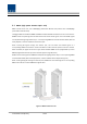
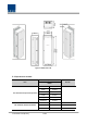
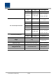
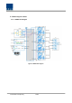
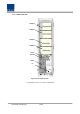
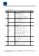
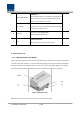
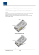
Table Of Contents
- Section1 Safety & Certification Notice
- Section2 System configuration and Functions
- 2.1 HROU (High power Remote Optic Unit)
- 2.1.1 Specifications of HROU
- 2.1.2 Block Diagram of HROU
- 2.1.2.1 HMRU block diagram
- 2.1.2.2 HROU inner look
- 2.1.2.3 HROU part list
- 2.1.3 Function by unit
- 2.1.3.1 High Remote Drive Unit (HRDU)
- 2.1.3.2 Remote Power Supply Unit ( RPSU)
- 2.1.3.3 Remote Optic(ROPTIC)
- 2.1.3.4 Remote Central Processor Unit (RCPU)
- 2.1.3.5 Multiplexer
- 2.1.3.6 System interface unit (SIU)
- 2.1.4 Bottom of HROU
- 2.1.4.1 Functions
- 2.1 HROU (High power Remote Optic Unit)
- Section3 System Installation

Confidential & Proprietary 16/44
2.1.2.3 HROU part list
No. Unit Description Remark
1 HRDU X4
High Remote Drive Unit
Consist of UDCU, PAU and cavity filter
Filter and high amplify TX signals;
Filter and amplify RX signals in low noise amplifier;
Remove out-of signals through cavity duplexer
Optional
Max 4
2
RPSU(AC)
Remote Power Supply Unit
Input power: 110 VAC/220VAC (85~264V)
Output power: +29 VDC
RPSU(DC)
Remote Power Supply Unit
Input power: -48 VDC(-40.8 ~ -57.6V)
Output power: +29 VDC
3 R-OPTIC
Remote Optic
Make RF conversion of TX optical signals;
Convert RX RF signals into optical signals;
Compensates optical loss;
5dBo optical link between ODU(OM4) and ROU;
10dBo optical link between ODU(OM1) and ROU;
Fiber Connector: SC/APC Connector;
Optical Wavelength: 1310/1550 WDM;
Communicates with BIU/OEU though the FSK modem
4 RCPU
Remote Central Processor Unit
Controls signal of each unit
Monitors BIU/ODU/OEU status through FSK modem
communication
5 CU1-L7085IC19P21A
Multiplexer1
This integrated combiner unit combines all bands for
output to a single antenna connection.