
User's Manual

Confidential & Proprietary 16/49
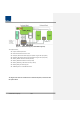
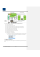
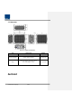
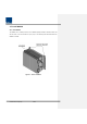
4.1 Installation
This chapter describes how to install each unit and optical cables. It also explains how to install
shelves or enclosuers of each unit, power cabling method and optical cabling and RF interface.
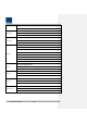
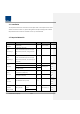
Required accessories and tools for installation are list up in the below table.
4.2 Required Materials
Installation Step
Accessory
Included
Tool
Remark
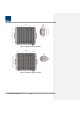
Remote Enclosure
Installation
M12 Bolt (4EA) X Spanner (19mm) -
Power
Connection_AC
AC 120V power cable (1EA)
[2 meter, with MIL-5015 type Connector (MS-
3106A- 18-10S) at one end, AC Plug at another
end]
○
- -
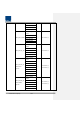
Power
Connection_DC
DC -48V power cable (1EA)
[2 meter, with MIL-5015 type Connector (MS-
3106A- 18-10S) at one end, 4.5 ø square lugs at
another end]
○
- -
Ground
Connection
M6 Screw (1EA)
○
#2 Screwdriver (+)
For more
details,
refer to
4.3.3.
Lug (1EA)
○
Crimping tool
Max. AWG #6 Cable X
Optical
Connection
Optical Cable Assembly Connector (1EA)
[957-5004-105, by Amphenol]
○
-
For more
details,
refer to
4.3.4.
OPTIC SC/APC Cable (1EA) X -
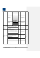
Antenna
Connection
4.3-10 DIN(M) RF Cable (1 or 2EA) X -
2 EA are
required in
case of
MIMO.
N2RDU
Installation
(Optional bands)
N2RDU_2500TDD
N2RDU_2500TDD
Module
○
#1 Screwdriver (+)
For more
details,
refer to
M4 Screw (6EA)