
User's Manual

C
onfidential & Proprietary
Note that BIU does not operate if the "+" terminal and the "
ar
e not inserted into the accurate polarity.
When you connect -
48V power with BIU, use the ON/OFF switch of MPSU located at the front
of BIU to check the power.
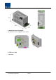
5.1.3
RF Interface at BIU
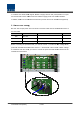
BIU can be connected with Bi
To connect BIU with BDA, you need to use a duplexer or a circulator to separate TX/RX signals
from each other.
BIU can feed external TX/RX signals from the Back Plane.
Using
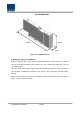
MDBU separated from each carrier band, BIU can easily expand and interface with bands.
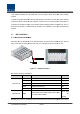
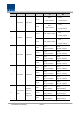
As seen in the table below, MDBU is divided into Single and Dual Bands. The unit can be
connected with two to four carrier signals per band. At the rear, #1~4 marks are
per MDBU. The following table shows signals to be fed to corresponding ports:
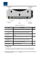
No Unit naming
Description
Power Switch
O
onfidential & Proprietary
72/139
Note that BIU does not operate if the "+" terminal and the "
–
" terminal of the
e not inserted into the accurate polarity.
48V power with BIU, use the ON/OFF switch of MPSU located at the front
RF Interface at BIU
BIU can be connected with Bi
-
Directional Amplifier and Base Station Tranceiver.
To connect BIU with BDA, you need to use a duplexer or a circulator to separate TX/RX signals
BIU can feed external TX/RX signals from the Back Plane.
MDBU separated from each carrier band, BIU can easily expand and interface with bands.
As seen in the table below, MDBU is divided into Single and Dual Bands. The unit can be
connected with two to four carrier signals per band. At the rear, #1~4 marks are
per MDBU. The following table shows signals to be fed to corresponding ports:
Description
In/out RF Port
Power Switch
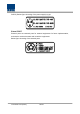
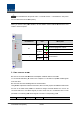
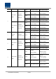
LED
Description
O
ON
Abnormal, Not supply Power
Normal supply power
DC ALM
Normal Status
Failure of output Power
I
ON
Normal Status
DC ALM
" terminal of the
-48V power
48V power with BIU, use the ON/OFF switch of MPSU located at the front
Directional Amplifier and Base Station Tranceiver.
To connect BIU with BDA, you need to use a duplexer or a circulator to separate TX/RX signals
MDBU separated from each carrier band, BIU can easily expand and interface with bands.
As seen in the table below, MDBU is divided into Single and Dual Bands. The unit can be
connected with two to four carrier signals per band. At the rear, #1~4 marks are
seen in order
per MDBU. The following table shows signals to be fed to corresponding ports:
In/out RF Port
Description
Abnormal, Not supply Power
-48Vdc
Normal supply power
-48Vdc
Failure of output Power