
User's Manual

C
onfidential & Proprietary
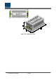
4.3.5
Front/rear panels of OEU
1)
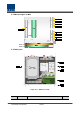
Front panel
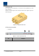
Figure 4.23
Item
1.EWDM LED
LED indicator
2.DOU LED
LED indicator to check DOU module state
3.System LED and Reset
Communication state with devices, alarm status of the system and reset
switch
4. NMS(RS-232C port)
RS
-
PC/laptop
wirings are limited to inside of the building
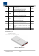
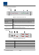
2) Rear panel
Figure 4.24
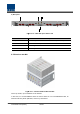
Item
1. GND Port
2. DC Input Port
3.power switch
4. To/From ODU Optic Port
5. To/From ROU Optic Port
onfidential & Proprietary
48/139
Front/rear panels of OEU
Figure 4.23
– OEU front panel Outer Look
Description
LED indicator
to check EWDM state to see if it is
abnormal
LED indicator to check DOU module state
to see if it is
Communication state with devices, alarm status of the system and reset
switch
-
232C
port for communication and diagnosis of devices through
PC/laptop
.
This equipment is indoor use and all the communication
wirings are limited to inside of the building
Figure 4.24
– Rear panel Outer Look
Description
Terminal for system ground
Input terminal for DC -48V
Power ON/OFF switch
SC/APC optical connector terminal
SC/APC optical connector terminal; use one optical cable per
abnormal
to see if it is
abnormal
Communication state with devices, alarm status of the system and reset
port for communication and diagnosis of devices through
This equipment is indoor use and all the communication
SC/APC optical connector terminal; use one optical cable per
ROU.