
User's Manual
C
onfidential & Proprietary
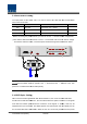
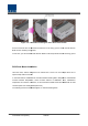
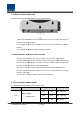
Figure 5.10 –
Installation flow diagram when AOR installs on wall
Put the
enclosure with the M5 Wrench Bolt fixed on the fixing groove and fix the M5 Wrench
Bolts into the remaining fixing holes.
In this case, you will use
6EA of
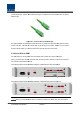
ROU Rack Mount Installation
Like other units, AOR
is designed to be inserted into a rack. The unit occupies
space except cable connection.
In case that AOR is installed more close above
increase ambient temperature, which increas
temperature is increased. T
herefore, w
constant space from existing ROU(above 2U)
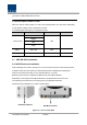
The following shows the installed diagram on rack with exisiting ROU
onfidential & Proprietary
108/139
Installation flow diagram when AOR installs on wall
enclosure with the M5 Wrench Bolt fixed on the fixing groove and fix the M5 Wrench
Bolts into the remaining fixing holes.
6EA of
M5 Wrench Bolts in total except bolts used for the fixing groove.
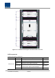
ROU Rack Mount Installation
is designed to be inserted into a rack. The unit occupies
space except cable connection.
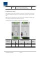
In case that AOR is installed more close above
/below
existing ROU, temperature of ROU
increase ambient temperature, which increas
e ambient of AOR
/ROU. Then, AOR/ROU
herefore, w
e recommend that AOR should be
installed with at least
constant space from existing ROU(above 2U)
The following shows the installed diagram on rack with exisiting ROU
Installation flow diagram when AOR installs on wall
enclosure with the M5 Wrench Bolt fixed on the fixing groove and fix the M5 Wrench
M5 Wrench Bolts in total except bolts used for the fixing groove.
is designed to be inserted into a rack. The unit occupies
about 4U of
existing ROU, temperature of ROU
/AOR
/ROU. Then, AOR/ROU
’s
installed with at least