
User's Manual

C
onfidential & Proprietary
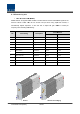
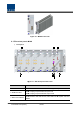
4. NMS(RS-232C port)
RS-
232C port for communication and diagnosis of devices through
PC/laptop
5. NMS(Ethernet port)
Ethernet port for upper network
This equipment is indoor use and all the communication wirings are
limited to inside of the
6. Pwr Test Port & ALM
Output DC power test port and ALM LED to show abnormal state, if any
7. Power switch
Power ON/OFF switch
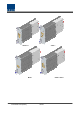
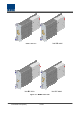
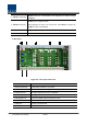
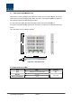
2) Rear panel
Figure 4.8
Item
1. External ALM Port
2. GSM Modem Port
3. V/UHF I/O Port
4. ODU I/O Port
5. ODU signal Port
6. BTS/BDA I/O Port
7. GND Port
8. DC Input Port
onfidential & Proprietary
35/139
232C port for communication and diagnosis of devices through
PC/laptop
Ethernet port for upper network
This equipment is indoor use and all the communication wirings are
limited to inside of the
building
Output DC power test port and ALM LED to show abnormal state, if any
Power ON/OFF switch
Figure 4.8
– Rear panel Outer Look
Description
Input/output terminal for dry contact
GSM Modem terminal for upper network (Optional)
RF signal interface terminal of VHF&UHF
RF signal interface terminal for ODU
Power and signal interface terminal for ODU
Input/output interface terminal of BTS/BDA
System ground terminal
Input terminal for DC -48V
232C port for communication and diagnosis of devices through
This equipment is indoor use and all the communication wirings are
Output DC power test port and ALM LED to show abnormal state, if any
GSM Modem terminal for upper network (Optional)