
User's Manual
Confidential&Proprietary107/115 SC‐DAS
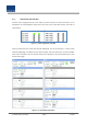
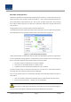
After turning on the switch of the power supply in the OEU, check information on each
module'sLEDofthesystem.The tablebelowshowsnormal/abnormalcasesdependingon
thestatusofeachmodule'sLED.
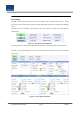
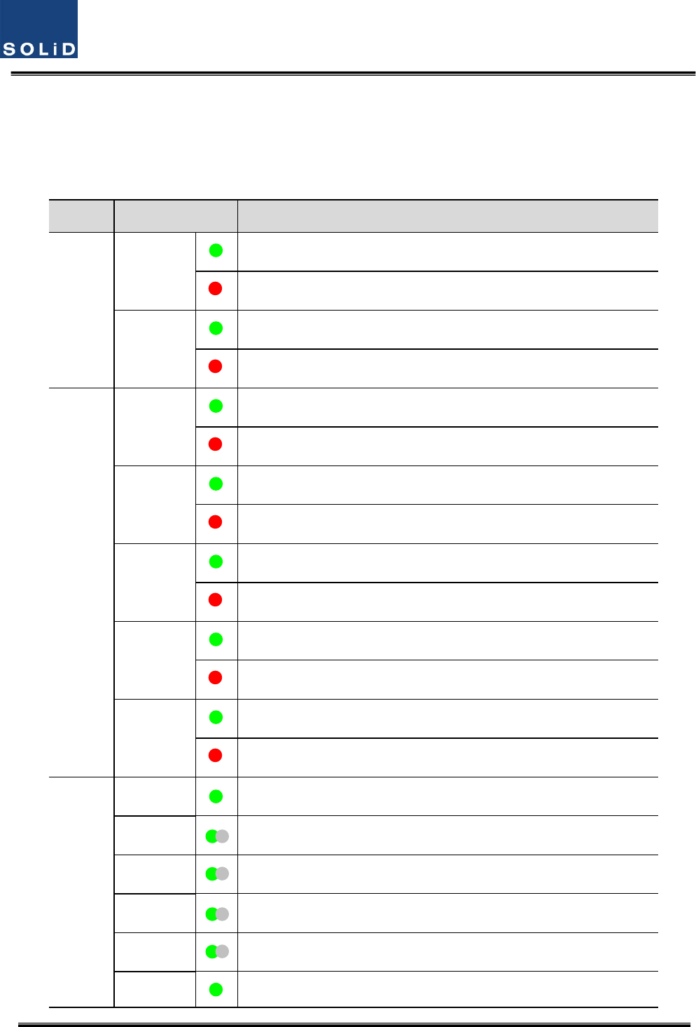
Unit LED Indicates
EWDM
LD
Green:LaserDiodenormalstatus
Red:LaserDiodeabnormalstatus
PD
Green:PhotoDiodenormalstatus
Red:PhotoDiodeabnormalstatus,inputopticpowerlowalarm
DOU1,2
LD
Green:LaserDiodenormalstatus
Red:LaserDiodeabnormalstatus
PD1
Green:PhotoDiode(PD)ofopticport1isnormal
Red:PDofopticport1isabnormalorinputopticpowerlow
PD2
Green:PhotoDiode(PD)ofopticport2isnormal
Red:PDofopticport2isabnormalorinputopticpowerlow
PD3
Green:PhotoDiode(PD)ofopticport3isnormal
Red:PDofopticport3isabnormalorinputopticpowerlow
PD4
Green:PhotoDiode(PD)ofopticport4isnormal
Red:PDofopticport4isabnormalorinputopticpowerlow
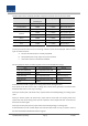
System
ON
Green:Poweron
TXD1
Greenflicker:ECPUsendNMSTxdatatoBIU
RXD1
Greenflicker:ECPUreceiveNMSRxdatafromBIU
TXD2
Greenflicker:ECPUsendNMSTxdatatoROU
RXD2
Greenflicker:ECPUreceiveNMSRxdatafromROU
ALM
Green:OEUsystemnormal(noalarm)