SC‐DAS Installation and Operation Manual Document Reference: Version: V5.0 Document Status: Release 5 Issue Date: Feb.
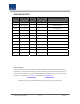
REVISION HISTORY No. of Pages Version Issue Date Initials Details of Revision Changes V 1.0 April. 11, 2011 V 2.0 Dec. 08,2011 Add Sprint band V 3.0 Jan. 06,2012 Add Sprint band V 4.0 Jan. 07,2013 Add VzW (MRU MIMO) band V 5.0 Feb. 13,2013 Add PS (MRU) band Original Technical Support SOLiD serial numbers must be available to authorize technical support and/or to establish a return authorization for defective units.
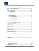
Contents Section1 Safety & Certification Notice....................................................................... 12 Section2 System Overview ....................................................................................... 15 2.1 General overview ............................................................................................ 16 2.2 System overview............................................................................................. 18 Section3 3.
.3.2 OEU block diagram ................................................................................... 43 4.3.3 OEU assemblies ....................................................................................................... 43 4.3.4Sub Assembly description ........................................................................................ 44 4.3.5 OEU front/rear panel overview.................................................................. 47 4.4 ROU (Remote Optic Unit) ..............
.3 ROU Installation .............................................................................................. 76 5.3.1 ROU Enclosure installation .............................................................................. 76 5.3.2 ROU Power Cabling ......................................................................................... 83 5.3.3 Optical Cabling ................................................................................................ 84 5.3.4 GND Terminal Connection .........
Confidential & Proprietary 6/117 SC‐DAS
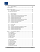
Figures Figure 1.1 – Basic system topology supporting SISO configuration ...................... 18 Figure 2.2 – Basic system topology supporting MIMO configuration .................. 18 Figure 2.3 – Expansion system topology supporting SISO configuration ............. 20 Figure 2.4 – Expansion system topology supporting MIMO configuration .......... 20 Figure 4.1 – BIU front and side views ................................................................. 26 Figure 4.2 – BIU block diagram ...................
Figure 4.20 – OEU at a glance ........................................................................... 42 Figure 4.21 – OEU block diagram ....................................................................... 43 Figure 4.22 – OEU internal view ........................................................................ 43 Figure 4.23 – DOU at a glance ........................................................................... 44 Figure 4.24 – EWDM at a glance ................................................
Figure 4.42 – ROU Top View for MRU 1900P+850C and ARU 700LTE+AWS‐1 ....... 60 Figure 4.42 – ROU Top View for MRU 1900P and ARU 900I+800I ....................... 60 Figure 4.44 – ROU Top View for MRU700LTE+AWS‐1 ......................................... 61 Figure 4.45 – ROU Top View for MRU700PS+800PS ........................................... 61 Figure 5.1 – RACK Installation............................................................................ 63 Figure 5.2 – Power interface diagrm .................
Figure 5.21 – ROU installation diagram for horizontal rack ................................. 82 Figure 5.22 – ROU Power Port view ................................................................... 83 Figure 5.23 – ROU optical Port view .................................................................. 84 Figure 5.24 – ROU GND Port view ..................................................................... 85 Figure 5.25 – ROU LED indicator information .....................................................
Figure 6.17 –OEU Optical information .............................................................. 111 Figure 7.1 –Shutdown logic diagram ................................................................ 114 Figure 7.2 –Optical loss information ................................................................
Section1 Safety & Certification Notice Confidential & Proprietary 12/117 SC‐DAS
“Only qualified personnel are allowed to handle this unit. Read and obey all the warning labels attached in this user manual” Any personnel involved in installation, operation or service of the SOLiD Technology repeaters must understand and obey the following: ‐ Obey all general and regional installation and safety regulations relating to work on high voltage installations, as well as regulations covering correct use of tools and personal protective equipment.
‐ Any DAS system or Fiber BDA will generate radio (RF) signals and continuously emit RF energy. Avoid prolonged exposure to the antennas. SOLiD recommends maintaining a 34.0cm (13.4 inches) minimum clearance from the antenna while the system is operating.
Section2 System Overview 2.1 General overview 2.
2.1 General overview SC‐DAS platform is a coverage system for in‐building services delivering seamless, high quality voice and data As a distributed antenna system, it provides analog and digital phone services in multiple bands through one antenna. The system covers public and private venues such as: Shopping malls Hotels Campus areas Airports Clinics Subways Multi‐use stadiums, convention centers, etc.
Support multi‐operator in a band(Max. 2 operator) Low OPEX / CAPEX Compact design Upgradable design Easy installation and maintenance Adopts auto ID scheme The SC‐DAS platform will serve two primary segments; first as a carrier deployed coverage enhancement product for their specific frequencies and second as a low cost, public safety / single carrier product.
2.2 System overview SC‐DAS comprises the components listed below. The base system consists of a BIU (BTS Interfcace Unit), an ODU (Optic distribution Unit) and a ROU (Remote Optic Unit). For use with multiple ROU’s, it has OEU (Optic Expansion Unit). The BIU has two layer which support both SISO and MIMO configuration using separate optical fiber cable. Fig2.1 shows basic system topology for SISO Figure 1.1 – Basic system topology supporting SISO configuration Figure 2.
As shown at Fig.’s 2.1 and 2.2, one strand of fiber is needed for SISO configuration but two strands are needed for MIMO cofiguration when connected with an ROU. Applications requiring up to 32ROU’s for SISO are possible with one BIU. Each SISO ROU will require an additional strand of fiber and an additional 32 ROU’s can be added to the same system for MIMO applications. MIMO requires 2 strands of fiber per ROU as well as MIMO specific ODU’s.
To reduce number of optical cables between multi‐building applications, we can utilize the OEU(Optical Expansion Unit) Fig 2.3 shows expansion system topology supporting SISO configuration using OEUs Figure 2.3 – Expansion system topology supporting SISO configuration Figure 2.4 – Expansion system topology supporting MIMO configuration Fig 2.
Section3 System Specifications 3.1 System specifications 3.1.1 Physical Specifications 3.1.2 Optic wavelength and Laser power 3.1.3 Environmental specifications 3.1.4 Available frequency bands 3.1.
3.1 System specifications 3.1.
3.1.2 Optical wavelength and Laser power Parameter ODU OEU ROU West optic TX: 1310nm TX: 1550nm, RX: 1550nm East optic RX: 1310nm TX: 1550nm Optical Wavelength RX: 1310nm TX: 1310nm, RX: 1550nm 1dBm±1dBm to ROU Output power 1.5dBm±1dBm to ROU,OEU 7dBm±1dBm to ODU 7dBm±1dBm to ODU Return loss <45dB <45dB <45dB 3.1.3 Environmental specifications Parameter BIU, ODU, OEU Operating Temperature ‐10 Operating Humidity, non condensing ‐ to +50°C ROU/AOR ‐10 to +50°C 5% to 90% 3.1.
3.1.5 Band Specifications SC‐DAS platform allows many band combinations as well as different output power levels within the band depending on the combination.
Section4 System Configuration and Functions 4.1 BIU (BTS Interface Unit) 4.2 ODU (Optic distribution Unit) 4.3 OEU (Optic Expansion Unit 4.
4.1 BIU (BTS Interface Unit) The BIU receives signals from the BTS or BDA through coaxial cable and transmits to four ODUs (Optic Distribution Unit).and The BIU separates RX signals received from ODUs according to their frequency band. Figure 4.1 – BIU front and side views 4.1.1 BIU Specifications Item Spec. Remark Size 482.6(19”) x 221.
4.1.2 BIU block diagram MCPU SISO SISO MIMO MIMO SISO MCDU ( ) MIMO MCDU ( M th B MPSU ) d Figure 4.2 – BIU block diagram 4.1.3 BIU assemblies Figure 4.
No.
No Unit naming In/out RF Port Description TX RX 1 1900P+850C Dual Band 4 Port 4 Port 2 700LTE+AWS‐1 Dual Band 4 Port 4 Port 3 1900P Single Band 2 Port 2 Port 4 900I+800I Dual Band 4 Port 4 Port 5 700PS+800PS Dual Band 4 Port 4 Port 6 1900P+AWS‐1 Dual Band 4 Port 4 Port 2 Port 2 Port 7 900I On the loadmap Dual Band Figure 4.
Figure 4.5 – MCDU at a glance VHF+UHF frequency band includes the following: for use in future No 1 Unit naming VHF+UHF Description Dual Band In/out RF Port TX RX 1 Port 1 Port 3) Main Central Processor Unit (MCPU) MCPU can inquire and control the state of the modules that are installed in the BIU. This unit can inquire and control the state of up to four ODUs. Through communication, it also can inquire and control ROUs that are connected.
Figure 4.6 – MCPU at a glance In the Main Central Processor Unit, a lithium battery is installed for RTC (Real Time Control) function. CAUTION RISK OF EXPLOSION MAY OCCUR IF BATTERY IS REPLACED BY AN INCORRECT TYPE DIPOSE OF USED BATTERIES ACCORDING TO THE INSTRUCTIONS [INSTRUCTION] The equipment and accessories including inner lithium battery are to be disposed of safely after the life span of them according to the national regulation.
Figure 4.7 – MPSU at a glance 4.1.5 BIU front/rear panel overview 1) Front panel Figure 4.8 – BIU front panel view Item 1. Alarm LED & Reset Description Communication state with devices, alarm status of the system and reset switch USB port for communication and diagnosis of devices through PC/laptop 2. DEBUG (USB B) This equipment isfor indoor use only and all the communication wirings are limited to indoor use as well. 3.
5. RF Monitor Port 20dB Coupling compared with TX Input Level 20dB Coupling compared with RX Output Level 6. Pwr Test Port & ALM Output DC power test port and ALM LED to show abnormal state, if any 7.
2) Rear panel 3 4 5 6 8 10 MIMO SIDE 2 1 9 SISO SIDE 7 11 Figure 4.9 – Rear panel view Item Description 1. DC Input Port Input terminal for DC ‐48V 2. External ALM Port Input/output terminal for dry contact 3. GND Port System ground terminal 4. AUX I/O Port Reserved Port for future uses 5. MIMO ODU I/O Port RF signal interface terminal for ODU 6. MIMO ODU signal Port Power and signal interface terminal for ODU 7. MIMO BTS/BDA I/O Port Input/output interface terminal of BTS/BDA 8.
4.2 ODU (Optic distribution Unit) ODU receives TX RF signals from upper BIU and converts them into optical signals. The optical signals are sent to ROU through optical cables. This unit converts optical signals from ROU into RF signals and sends the converted signals to BIU. For each shelf of the ODU, up to two DOUs (Donor Optic Unit) can be installed in it. One DOU is supported with four optical ports. Therefore, one ODU can be connected with eight ROUs.
4.2.2 ODU block diagram Figure 4.11 – ODU block diagram 4.2.
Figure 4.12 – ODU Internal View No. Unit Description Remark Donor Optic Unit 1 DOU Converts TX RF signals into optical signals; Converts RX optical signals into RF signals; Max 2 ea. Provides up to four optical ports per DOU 2Way Divider 2 2W Divides TX RF signals into two; Combines two RX RF signals into one 3 DU 4 Shelf 5 Accessories Distribution Unit Distributes power and signals to DOU 19” rack, 1RU 25PIN DSUB, Male to female 1pcs RF Coaxial Cable Assembly 2pcs 4.2.
Figure 4.13 – DOU at a glance 2) 2Way Divider (2W) The 2 way divider is equipped with two 2‐way splitters in a single housing and the splitters work for TX/RX signals, respectively. Designed in broadband type, the divider combines and splits signals from/to the BIU Figure 4.14 – 2Way Divider at a glance 4.2.
Figure 4.15 – ODU front panel view Item 1,2 Description LED indicator to check for faulty DOU module. 2) Rear panel Figure 4.16 – ODU Rear panel view Item Description 1. Optic Port SC/APC optical connector terminal; use one optical cable per ROU. 2. DC I/O Port Terminal for power and state values 3. RX RF Port RX RF signal interface terminal 4.