
User's Manual


Confidential&Proprietary73/122 SC‐DAS
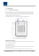
5.2 ODUInstallation
ODUshouldbe,inanycase,putonthetopofBIU.ThisunitgetsrequiredpowerandRFsignalsfrom
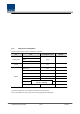
BIU.ThefollowingtableshowscomponentsofODU:
No. Unit Description Remark
Shelf IncludingMainBoard,19”,1U 1EA
RFCable SMA(F)toSMA(F),400mm 2EA
CommonPart
SignalCable 3Row(26P_F)to3Row(26P_M),650mm 1EA
OptionalPart DOU OpticalModulewith4OpticPort
Up to 2EA to be
inserted
5.2.1 ODUShelfInstallation
The ODU chassis is 1RU in height and 19” wide. It should be inserted into a 19” standard rack and
placedabovetheBIUleavinga1RUgapbetweentheODUandtheBIU.
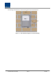
5.2.2 ODUPowerCabling
TheODUgetspowerfromtheBIU.
When youconnect a3‐Row,26‐pin D‐SUB Signal cable from BIU and install DOU, LED on the front
panelislit.ThroughthisLED,youcancheckstatevaluesofLDandPDofDOU.
5.2.3 ODUOpticCabling
The ODU makes RF‐optical conversion of TX signals as well as optical‐RF conversion of RX signals.
TheODU can be equipped with up to two DOUs. One DOU supports four optical ports and one
optical port can be connected with an ROU. Optionally, only optical port 4 can be connected with
OEUforODU1andODU2.ODU3.ODU4cannotconnectwithOEU.
AsWDM isused intheDOU,theunit canconcurrently sendandreceivetwo differentwavelengths
(TX:1310nm,RX:1550nm)throughonestrandoffiber.TheDOUhasSC/APCfiberconnectors.