
User's Manual

Confidential&Proprietary30/122 SC‐DAS
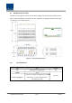
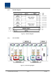
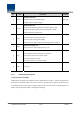
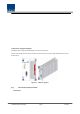
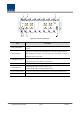
Figure4.8–BIUfrontpanelview
Item Description
1.AlarmLED&Reset
Communication state with devices, alarm status of the system and reset
switch
2.DEBUG(USBB)
USBportforcommunicationanddiagnosisofdevicesthroughPC/laptop
Thisequipment isforindooruseonly andallthecommunicationwirings are
limitedtoindooruseaswell.
3.NMS(Ethernetport)
Ethernetportforuppernetwork
ThesupportingnetworkmodeisUDPprotocol
4.MDBULED LEDtoshowwhetherMDBUisinstalledandisoperatingproperly
5.RFMonitorPort
20dBCouplingcomparedwithTXInputLevel
20dBCouplingcomparedwithRXOutputLevel
6.PwrTestPort&ALM OutputDCpowertestportandALMLEDtoshowabnormalstate,ifany
7.Powerswitch PowerON/OFFswitch