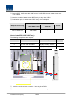
ྚ Connect BPF 1900P port with 1900P port of 1900P RDU through 1900P+AWS-1 RF01 RF CABLE. ྛ Insert the combined 1900P+AWS-1 BPF Ass’y into any slot of ROU. ྜ Combination point of 1900P+AWS-1 BPF Ass’y of the multiplexer Interface Point Multiplexer Port naming Remark 1900P+AWS-1 RDU AWS-1+1900P COM 1900P BPF 1900P+AWS - How to install RDU VHF+UHF Ass’y The following components are required: No.
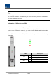
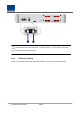
You cannot insert the same module and band into MULTIPLEXER port at the same time. For example, you are not supposed to insert both of 800PS RDU and 800PS+900I+PA RDU into ROU at the same time. In the same way, you cannot concurrently insert both of 850C RDU and 850C+700PS RDU into ROU. Information of LED at the front RDU RDU has the structure of enabling a random RDU to be inserted into three slots. ROU can be equipped with a total of three RDUs.
Up to three RDUs can be inserted. If one or two units are used, then you need to terminate the unused slot of RDU with a BLANK card. 5.3.
For power consumption of ROU, the common part consumes 17W. Depending on the quantity of each RDU, you can add overall power consumption of ROU. Only, in case of Dual-Band signals, power consumption is calculated respectively when HPA of the other party is turned OFF and two HPA devices are turned ON. Note that when you calculate Power Budget. 5.4 OEU Installation OEU is used to expand ROU in Campus Site. OEU is located at a Remote Closet.
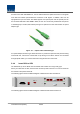
Note that OEU does not operate if the "+" terminal and the "–" terminal of the -48V power are not inserted into the accurate polarity. 5.4.3 OEU Optic Cabling OEU is connected with upper ODU. With DOU inserted in it, the unit is connected with ROU.
As OEU has a shelf with EWDM in it, the unit makes electronic-optical conversion of TX signals from ODU and makes optical-electronic conversion of RX signals. In addition, OEU can be equipped with up to two DOUs. One DOU supports four optical ports and one optical port can be connected with ROU. With WDM in DOU, the unit can concurrently send/receive two pieces of wavelength (TX:1310nm, RX:1550nm) through one optical core. DOU has SC/APC of optical adaptor type. Figure 5.
When you insert DOU into OEU, insert the unit into the top DOU1 first. For unused slots, you nedd to install BLANK UNIT into them. 5.4.5 Consumption Power of OEU OEU has -48V DC Power supply in it. ODU can be equipped with up to two DOUs. Depending on the quantity of DOU, power consumption is varied. The following table shows power consumption of OEU: Part Unit Consumption Power Remark Shelf EWDM Common Part 12W ERF EPSU OEU_4 DOU 1 EA 23W OEU_8 DOU 2 EA 33W 5.
Section6 Operation 6.1͑ BIU Operation͑ 6.
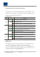
This chapter describes operation of SMDR-NH124. It deals with procedures and operations for normal system operation after installation. It also describes operations per unit and interworking methods. 6.1 BIU Operation 6.1.1 BIU 6.1.2 TX Operation at BIU TX level to be sent to BIU should be in the range of -20dBm ~ + 10dBm. If the level exceeds the range, you need to connect an attenuator with the front end of BIU input and adjust the level in the corresponding range.
Checking the status of the system's LED Indicator After turning on the switch of the power supply in BIU, check information on each module's LED of the system. The table below shows normal/abnormal cases depending on the status of each module's LED. LED information Unit LED ON MDBU Indicates Green: MDBU is normally power-supplied. Green: MDBU is normal. ALM Red: MDBU is abnormal; check the alarm through RS-232C. MCPU ON Green: MCPU is normally power-supplied.
Check if MDBU is inserted into a corresponding slot of BIU. The ID screen shows the following: A. MDBU ID: 800Public Safety, 800PS+900I+Paging, 850C, 700PS+850C, AWS-1,1900P B. Not Insert: This status value appears when MDBU has not been set. C. Link Fail: This status value appears when MDBU has been set but it fails to communicate with modules. Use the ON/OFF (Activation/de-activation) function for a port you want to use and turn it ON. Depneding on whether to use a port, output varies.
AWS-1 26dBm-10*LOG(N) 4 VHF 24dBm-10*LOG(N) 1 UHF 24dBm-10*LOG(N) 1 Check if the level of TX IN POWER is the same as the value measured through spectrum (Within ·3dB). Use TX IN AGC function and automatically set internal ATT depending on input level. ATT is automatically set based on -20dBm of input . The table below shows TX IN ATT depending on TX IN POWER. For manual setting, you can set ATT depending on input according to the table.
Use various upper/lower limits. The following table shows recommended limit settings: Item Recommended Limit Remark TX IN HIGH ALM 15dBm Alarm TX IN LOW ALM -25dBm Alarm RX OUT ALC 0dBm Auto Level control RX OUT HIGH ALM 5dBm Alarm As such, when you finish setting normal input levels and alarm limits, check if the value of MODULE FAILUER LED Indicator is lit green (Normal case). 6.1.
setting makes BIU actually try to communicate with lower units while collecting the status value of units. The menu below shows INSTALL menu, where you can see topology for overall units at a glance. Overall topology for SMDR-NH124 Configuration of BIU-ODU-ROU Configuration on whether to use BIU varies depending on the topology above and so you need to check on a unit to be installed. Ex.
1. Select INSTALL from GUI menu. 2. Check on ODU1 menu>DOU1>ROU1. 3. Close the INSTALL menu. 4. Check if ROU is created, which was checked on at the left TREE panel. 6.1.5 ODU Operation at BIU BIU can be equipped with up to four ODUs. One ODU can hold two DOUs in it. For information on insertion/deletion of DOU in ODU, you can see at the main window of BIU.
When you select ODU screen from the left TREE panel, you can see DOU1 or DOU2 menu actiavted depending on whether DOU has been inserted. Then, the optical port set at the INSTALL menu is also actiavted to let you check PD value of the optical port. Any optical port not set at the INSTALL menu is seen de-activated in grey. The level of Laser diode received from ROU/OEU is +7dBm·0.5dB.
In general, the level of optical PD POWER should be +6dBm~ +2dBm·1.5dB. What is more, ODU has the function of automatically compensating for optical cables. The following procedure is related to how to make optical compensation with ROU connected with port, at a corresponding DOU window of ODU: 1. Check if ODU is smoothly communicating with a corresponding ROU. 2. Select ODU or DOU from the left Tree panel. 3. Set “RX OPTIC COMP” of the optical port of a corresponding DOU as "ON." 4.
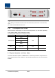
And it can be installed on a wall or into a rack. Basically, one antenna is provided. To install a variety of antennas, you need such devices as a divider and a coupler. ROU can work with a DC Feeder and an Optic Cable Feeder. For power supply of ROU, a power supply in AC-DC and DC-DC type is provided to let you select a power supply suitable for an application. For upper level, ROU can be connected with ODU and OEU. It has AGC function for 5dBo of optical cable loss.
ALM Normal Operation Abnormal Operation RPSU ON The power is not supplied or the polarity of -48V is reversed. The power is supplied. ID Setting Use an RS-232 Cable(Direct Cable) for connection with DEBUG port of ROU RCPU. Execute GUI (Graphic User Interface). When you connect ROU directly with a Serial port, the screen will show the TREE of a direct line of units connected with ROU. Basic ROU ID is set as ODU1DOU1-ROU1. Set it with the ID of a designed ROU.
ROU Optic Comp Operation ROU has the function of automatically compensating for optical loss. It can do the work for up to 5dBo of optical loss. Set “TX OPTIC COMP” of ROU as "ON." Optical compensation of ROU can not be made without communication with such units in upper level as ODU or OEU. For 1dBo of optical loss, basic TX OPTIC ATT is 12dB; for 5dBo of optical loss, TX OPTIC ATT is 4dB. OPTIC COMP works only one time before it stays dormant.
Through GUI, check if the ID of RDU module is inquired at LEFT, MIDDLE and RIGHT slots of RDU. When you select the tab of a corresponding slot (LEFT, MIDDLE and RIGHT) from the main window of ROU, you can inquire and set the status of a corresponding RDU module. Set HPA of a corresponding RDU as “ON.” Use TX OUTPUT AGS function and set it as a desired output level.
B. Not Opterate OPTIC Comp: Optic Comp is not executed. C. Lack of ATT: There is no attenuation available. Use various upper/lower limits. The following table shows recommended limit settings: Item Recommended Limit Remark TX OUTPUT HIGH ALM Max Composit Power+1dB Alarm TX OUTPUT LOW ALM 0dBm Alarm TX OUTPUT ALC Max Composit Power Auto Level control TX OUTPUT SD Max Composit Power+2dB Shutdown RX ALC -45dBm If TX OUTPUT HIGH ALM is higher than a setting value, alarms will be genrated.