X-Rack Owner’s Manual
Solid State Logic S O U N D | | V I S I O N SUPERANALOGUE X-RACK Super-Analogue™ Outboard Owner’s Manual 82S6XR010C
X-Rack Owner’s Manual Solid State Logic S O U N D | | V I S I O N Begbroke, Oxford, England, OX5 1RU • +44 (0)1865 842300 320 West 46th Street, 2nd Floor, New York, NY 10036, USA • +1 (1) 212 315 1111 Suite 401, 5757 Wilshire Blvd, Los Angeles, CA 90036, USA • +1 (1) 323 549 9090 3-55-14 Sendagaya, Shibuya-Ku, Tokyo 151-0051, Japan • +81 (0)3 5474 1144 7 bis, rue de la Victoire, le Blanc Mesnil, Paris 93150, France • +33 (0)1 48 67 84 85 Via Timavo 34, 20124 Milano, Italy • +39 (0)39 2328 094 Visit SSL
Contents 1. 2. 3. 4. 5. A B D E F 2.1 2.2 2.3 2.4 3.1 3.2 3.3 3.3.1 3.3.2 3.3.3 3.3.4 3.3.5 4.1 4.2 4.2.1 4.2.2 4.2.3 4.2.4 4.2.5 4.2.6 4.3 4.3.1 4.3.2 4.4 4.4.1 4.4.2 4.4.3 4.4.4 4.4.5 4.4.6 4.4.7 4.5 5.1 5.2 5.3 5.
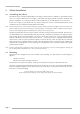
Page 2 30 HI 6 IN IN fl Serial No. 100-240 0.5-0.2 Ratings: AC ~ 50/60Hz Volts Am ps 629935X1 XRK001 30 NONE 6 Q LF - - 1 40 .2 .6 .6 2 1.5 Hz KHz IN KHz 5 15 600 220 2.0 1.6 1.0 G-EQ 7 3 22 10 CAUTION + 60 .3 + + 2 5 - Q HMF dB - dB SEL LF - - dB Q LMF dB RISK OF ELECTRIC SHOCK DO NOT OPEN dB Q LMF dB - + KHz HF XR625 1 2 + 60 .3 + + + 40 .2 .6 .6 2 TOTAL RECALL LINK OUT MIDI OUT MIDI IN Do not expose to rain or moisture.
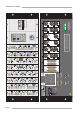
1. Introduction Introduction Overview The Solid State Logic X-Rack unit has been developed from the successful range of XLogic outboard equipment and provides a flexible solution to those engineers requiring a larger number of processing units in a compact package.
X-Rack Owner’s Manual 2. Safety considerations 2.1 Definitions This section contains definitions and warnings, and practical information to ensure a safe working environment. Please take time to read this section before undertaking any installation work. ‘Maintenance’ All maintenance must be carried out by fully trained personnel. Note: it is advisable to observe suitable ESD precautions when maintenance to any part is undertaken.
Safety Considerations Mains Supply and Phases Solid State Logic equipment is designed for connection to single phase supplies with the Neutral conductor at earth potential – category TN – and is fitted with a protective fuse in the Live conductor only. It is not designed for use with Phase (Live) and Neutral connections reversed or where the Neutral conductor is not at earth potential (TT or IT supplies).
X-Rack Owner’s Manual 3. 3.1 X-Rack Installation Assembling the X-Rack The X-Rack unit is normally shipped either as an empty rack (SSL Part No. 729935X1), a part filled (custom) rack or as a fully loaded unit; for example, a unit fitted with eight 729618X1 Dynamics modules (SSL Part No. 729935X2) – if you have purchased a fully loaded unit you should skip the rest of Section 3.1.
X-Rack Installation and Operation 3.3 Connection 3.3.1 Power Connection The X-Rack unit has an auto-sensing power supply that can operate on 100 – 230V without adjustment. The power connection is made via a standard IEC mains cord to an un-switched IEC mains socket on the rear panel and a latching power switch is provided on the front panel of the unit. 3.3.2 Audio Connection Generally, each module will have an input connector (normally a female XLR) and an output connector (normally a male XLR).
X-Rack Owner’s Manual 4. 4.1 Operation - Total Recall Overview The Total Recall computer stores all of the switch and rotary control positions for each X-Rack module in one of thirty two internal stores. These can be recalled and compared with the current settings using front panel LEDs to show which controls do not match. If the module layout has changed since the snapshot was taken, only the modules that match will be recalled.
X-Rack Installation and Operation 4.2.4 Copy/Swap While displaying a TR setup pressing and holding a module SEL switch and then pressing a second SEL switch will swap the setting of the two channels. Selecting COPY/DEL and then doing the same will copy settings from the first channel to the second. Note that Copy/Swap is only allowed between similar modules; the unit will not allow you to swap settings between an EQ module and a Dynamics module for instance! & SEL SEL COPY/ DEL 4.2.
X-Rack Owner’s Manual 4.4 Setup/MIDI Mode 4.4.1 Overview Enter SETUP/MIDI mode by holding down the SETUP/MIDI switch till the display reads ‘5e’. The SETUP/MIDI LED flashes to show you are in this mode. Press and hold the same switch to return to normal operation. Navigating in the Setup menu SETUP/ MIDI The setup menu contains a number of options. These each contain a number of sub-options. Turn the D-Pot to scroll through the main list of options and push the D-Pot to select an option for editing.
X-Rack Installation and Operation 4.4.2 MIDI (m1) Under this menu it is possible to set the MIDI controls which can control parts of the X-Rack XR622 Master module and also to save and load all internal stores to and from a MIDI sequencer or librarian as a SysEx dump. MIDI Remote Channel (ck) Under the MIDI menu, use the D-Pot to select MIDI Channel. Then press the D-Pot and turn it to select the required channel (‘01’ to ‘16’ or ‘al’ for all/any channel).
X-Rack Owner’s Manual • The display will show ‘5a’ and both the ‘SAVE’ LED and display flash. & SAVE • Create an additional MIDI track in your DAW program. Select its input and output to be the MIDI port connected to your X-Rack. • If available select the track to store System Exclusive data and record enable the MIDI track. • Press Play and Record on the DAW to put the MIDI track into record. • Press the SAVE switch to start transmission of all saved Total Recall setups.
X-Rack Installation and Operation When Remote Mode is set to MIDI (‘m1’), the ‘soft’ controls on the XR622 Master module may be remotely operated as MIDI controls. The Master module controls will continue to function until a valid MIDI packet has been received, after which all of the ‘soft’ controls will be locked out – operating these controls under these conditions will result in an ‘re’ message on the X-Rack display.
X-Rack Owner’s Manual 4.4.7 Show Version (ve) Select Show Version by turning the D-Pot till the display shows ‘ve’. Press the D-Pot to show the software version in three blocks. As an example, software version ‘V1.2/11’ will display in this sequence before returning to display ‘ve’. 4.4.8 Set DIM Level (d1) Select DIM Level by turning the D-Pot till the display shows ‘d1’. Press the D-Pot to show the current DIM level. The level can be varied from –3dB (‘03’) to –30dB (‘30’).
X-Rack Installation and Operation 4.5 Software Download and Installation Software to upgrade your X-Rack unit can be downloaded from the SSL website (http://www.solid-statelogic.com/plus/utilities.html). To access this page will you will need to be registered with us and logged into the website. The X-Rack software is packaged as a 50kB (approximately) Java archive file, the format of which is compatible with both PC and Macintosh (OS X only) platforms.
X-Rack Owner’s Manual 6. 7. 8. 9. Go to the Out MIDI Port menu. Select the MIDI OUT port which is connected to your X-Rack: Note that the Macintosh will show all MIDI Inputs at the top of the list, MIDI Outputs at the bottom. You must scroll to the middle of the list to see the MIDI Out ports. Click on the Test button. This transmits a packet of data to the X-Rack which should return an acknowledgment to the computer.
5. 5.1 X-Rack Installation and Operation Miscellaneous X-Rack Internal Links and Fuses 5.1.1 Fuses (Mains Inlet) The power supply module is internally fused. In the event of this fuse failing the entire unit should be returned to your nearest SSL Service agent. 5.1.2 Internal Fuses The internal power rail fuses will automatically reset once the fault condition has been removed and should not need to be replaced. 5.1.3 Links There are no user settable links. 5.
X-Rack Owner’s Manual X-Rack Connector Details (cont.
5.3 Physical Specification * Depth: 180mm / 7.2 inches 255mm / 10.2 inches excluding front panel knob(s) and connectors including connectors, excluding front panel knob(s) Height: 178mm / 7 inches (4 RU) excluding feet Weight: 2.8kg / 6.2 pounds 3.5kg / 7.7 pounds 5.0kg / 11 pounds without modules fitted with blank panels fitted with modules fitted Width: Power: Boxed size: Boxed weight: 440mm / 17.4 inches 483mm / 19 inches 50 Watts / 60VA 4.3kg / 9.5 pounds 5.0kg / 11 pounds 6.5kg / 14.
X-Rack Owner’s Manual Notes Page 20
X-Rack Mic Amp Module A. The Mic Amp Module A.1 Connection The rear panel of the module carries the Mic (‘IN’) and Line input (‘LINE’) XLRs along with a single output (‘OUT’) XLR. The Line input and output operate at a nominal level of +4dBu although the gain of the Line input can be varied by a front panel control. Also contained on the front panel is an additional mono Jack socket for a high impedance Instrument input. IN LINE OUT A.
X-Rack Owner’s Manual A.2.3 HF/LF Section 3 XR621 This section contains simple high and low pass filters as follows: HF (Low Pass): Frequency range 50kHz – 3kHz (–3dB point) Slope: 12dB/Octave LF (High Pass): Frequency range 30Hz – 600Hz (–3dB point) Slope: 18dB/Octave SEL MIC INST The two filters can be switched into circuit independently. A.2.
X-Rack Mic Amp Module A.3 Performance Specification The following pages contain audio performance specification figures for the X-Rack Mic Amp module. No other Solid State Logic products are covered by this document and the performance of other Solid State Logic products can not be inferred from the data contained herein. A.3.1 Measurement Conditions For each set of figures on the following pages, the specific unit and test setup will be stated at the beginning of that section.
X-Rack Owner’s Manual A.3.4 Instrument Input Performance Un-balanced signal applied to Instrument Input and measured at Output. Pad switched out and Input Gain control set to +12dB (minimum). Gain Continously variable from +12dB to +75dB Independently switchable 18dB Pad available Input Impedance 1MΩ Output Headroom > +26dBu at onset of clipping THD + Noise (-18dBu applied, +28dB gain) < 0.03% at 1kHz < 0.05% at 10kHz Frequency Response +0.05dB/-0.
X-Rack Mic Amp Module A.4 Calibration Information The X-Rack Mic Amp module is factory calibrated and should only need calibration if a potentiometer or other component has been replaced or if it is suspected that there is a problem with calibration. In each of the following instructions it is assumed that the lid of the X-Rack has been removed and that power has been applied.
X-Rack Owner’s Manual A.5 Connector Details Audio Input Audio Output Location: Rear Panel Location: Rear Panel Conn' Type: XLR Female Conn' Type: XLR Male Pin Description 1 Chassis Audio +ve Audio -ve 2 3 Pin Description 1 Chassis Audio +ve Audio -ve 2 3 Instrument Input Location: Front Panel Conn' Type: Mono 1/4" Jack Socket Pin Tip Sleeve Description Guitar Input Chassis A.6 Physical Specification * Depth: 200mm / 7.9 inches 275mm / 10.9 inches Height: 171mm / 6.
X-Rack EQ Module B. The EQ Module B.1 Connection The module input and output gains can be set to operate at a nominal level of either +4dBu or –10dBV, using a switch on the connector panel. To select the appropriate level for the equipment you are connecting to, please check the operating manual for your mixer or DAW. The switch should be released for +4dBu operation: push it in for –10dBV operation. IN -10dBV +4dBu OUT B.
X-Rack Owner’s Manual Page B-2
X-Rack EQ Module B.3 Performance Specification The following pages contain audio performance specification figures for the X-Rack EQ Module. No other Solid State Logic products are covered by this document and the performance of other Solid State Logic products can not be inferred from the data contained herein. B.3.1 Measurement Conditions For each set of figures on the following pages, the specific unit and test setup will be stated at the beginning of that section.
X-Rack Owner’s Manual LMF Band controls: Frequency Variable from 200Hz to 2.5kHz Gain Variable by > ±20dB ‘Q’ Variable from 0.5 to 2.5 (may also vary with gain) LF Band controls: Frequency Variable from 40Hz to 600Hz Gain Variable between ±16.5dB ‘Q’ 2.5 (on ‘ ’ setting) The LF and HF bands have variable turnover frequency with switchable bell/shelving and selectable response curves: Channel Equaliser Curves Amplitude (dBr) v Frequency (Hz) 25.0 ’E type’ 20.
X-Rack EQ Module B.4 Calibration Information The X-Rack EQ module is factory calibrated and should only need calibration if a potentiometer or other component has been replaced or if it is suspected that there is a problem with calibration. In each of the following instructions it is assumed that the lid of the X-Rack has been removed and that power has been applied.
X-Rack Owner’s Manual LF EQ - Maximum Gain Adjustment: 1. Set LF Gain to maximum and select LF . Set the audio oscillator for 80Hz and adjust LF Frequency to find the maximum level on the audio level meter. 2. Adjust VR14 (LF Q) for +16.5dBu ±0.25dB. 3. Reset LF Gain to its centre indent position, de-select LF the audio level meter for 0dBu. and re-check B.4.2 Output Balance Equipment Required: Calibrated audio oscillator, audio level meter and a ‘balance’ adaptor (see below).
X-Rack EQ Module B.5 Connector Details Audio Input Audio Output Location: Rear Panel Location: Rear Panel Conn' Type: XLR Female Conn' Type: XLR Male Pin Description 1 Chassis Audio +ve Audio -ve 2 3 Pin Description 1 Chassis Audio +ve Audio -ve 2 3 B.6 Physical Specification * Depth: 200mm / 7.9 inches 275mm / 10.9 inches including front panel knobs, excluding connectors including front panel knobs and connectors Height: 171mm / 6.75 inches Width: 35mm / 1.4 inches 49mm / 1.
X-Rack Owner’s Manual Page B-8
X-Rack Dynamics Module D. The Dynamics Module D.1 Connection The module input and output gains can be set to operate at a nominal level of either +4dBu or –10dBV, using a switch on the connector panel. Select the appropriate level for the equipment you are connecting to. If in doubt experiment! IN To check the input and output gains, set the compressor Ratio and Threshold controls fully clockwise and send a signal close to the nominal operating level of your mixer or DAW to the dynamics module.
X-Rack Owner’s Manual FST ATK – Normally, a controlled linear attack time of 1.5ms per 40dB is provided. Press this button to select a fast attack time (100µs per 40dB). The attack time is the time taken for the Gate/Expander to ‘recover’ once the signal level is above the threshold. When gating signals with a steep rising edge, such as drums, a slow attack may effectively mask the initial ‘THWACK’, so you should be aware of this when selecting the appropriate attack time.
X-Rack Dynamics Module D.3 Performance Specification The following pages contain audio performance specification figures for the X-Rack Dynamics Module. No other Solid State Logic products are covered by this document and the performance of other Solid State Logic products can not be inferred from the data contained herein. D.3.1 Measurement Conditions For each set of figures on the following pages, the specific unit and test setup will be stated at the beginning of that section.
X-Rack Owner’s Manual D.3.5 Measurement Conditions Signal applied to Input, output measured at Output. All pots anti-clockwise and switches ‘out’ except for Dynamics ‘in’. THD + N (+10dBu applied) < 0.01% at 1kHz Signal at +20dBu applied to Input, Compressor Threshold set at –20, Compressor Ratio adjusted to give +4dBu at Output. RMS sensing mode selected. THD + N (Fast Attack Mode) † < 0.3% at 1kHz < 0.05% at 10kHz THD + N (Slow Attack Mode) < 0.03% at 1kHz < 0.
X-Rack Dynamics Module D.4.3 Compressor Threshold Adjustment: 1. Connect the level meter to the Output and set the oscillator level for –28.35dBu. 2. Measure the DC voltage at test point TP14 relative to 0VA and adjust VR9 (COMP_THOLD) for 0V ±10mV. D.4.4 Compressor Law Adjustment: 1. Set the oscillator level for +20dBu. 2. Connect the level meter to the Output. Check for +20dBu ±0.5dB. 3. Set the compressor ratio control fully clockwise and press in the compressor FST ATT and PK switches. 4.
X-Rack Owner’s Manual D.5 Connector Details Audio Input Audio Output Location: Rear Panel Location: Rear Panel Conn' Type: XLR Female Conn' Type: XLR Male Pin Description 1 Chassis Audio +ve Audio -ve 2 3 Pin Description 1 Chassis Audio +ve Audio -ve 2 3 Key Input Location: Rear Panel Conn' Type: XLR Female Pin Description 1 Chassis Audio +ve Audio -ve 2 3 D.6 Physical Specification * Depth: 200mm / 7.9 inches 275mm / 10.9 inches Height: 171mm / 6.
E. E.1 E.2 E.3 The Line Return Module X-Rack Line Return Module Introduction The X-Rack Line Return module is designed to operate in conjunction with the X-Rack XR622 Master module to create an expandable, rack mounted, stereo line level mixer. The X-Rack Master module provides the monitoring facilities that would be expected; mix amps, monitor outputs and a headphone feed – please refer to the X-Rack Master module documentation for a full description.
X-Rack Owner’s Manual Page E-2
X-Rack Line Return Module E.4 Performance Specification The following page contains audio performance specification figures for the X-Rack Line Return module. No other Solid State Logic products are covered by this document and the performance of other Solid State Logic products can not be inferred from the data contained herein. E.4.1 Measurement Conditions For each set of figures on the following pages, the specific unit and test setup will be stated at the beginning of that section.
X-Rack Owner’s Manual E.5 Calibration Information The X-Rack Line Return module is factory calibrated and should only need calibration if a potentiometer or other component has been replaced or if it is suspected that there is a problem with calibration. In each of the following instructions it is assumed that an X-Rack Master module is also fitted to the X-Rack and that power has been applied.
X-Rack Line Return Module E.
X-Rack Owner’s Manual E.7 Physical Specification * Depth: Height: Width: Weight: Boxed size: Boxed weight: 200mm / 7.9 inches 275mm / 10.9 inches including front panel knobs, excluding connectors including front panel knobs and connectors 35mm / 1.4 inches 49mm / 1.9 inches front/rear panels overall width (front and rear panels are offset) 171mm / 6.75 inches 260g / 9.5 ounces 190mm x 290mm x 70mm / 7.5" x 11.5" x 2.5" 460g / 16.5 ounces * All values are approximate E.
F. F.1 The Master Module X-Rack Master Module Introduction Used in conjunction with the XR623 X-Rack Line Return module, the XR622 X-Rack Master module provides a complete small scale mix and monitor system for studios seeking a compact solution for mixing and monitoring in the analogue domain. A single X-Rack can provide up to 28 line level inputs.
X-Rack Owner’s Manual F.3.2 Monitor Section 2 The Monitor Section enables the Mix and Record busses or a stereo external input to be monitored, the source to monitor being set by either the ‘MIX’, ‘REC’ or ‘EXT’ switches either seperately or together, allowing great flexibility in recording and montitoring signals. The ‘EXT’ input would normally be playback from the main recorder or DAW.
X-Rack Master Module • Use the D-Pot to select ‘le’ (MIDI Remote Learn) and press SAVE to enable learn mode. • Operate any one of the ‘soft’ controls on the XR622 Master module. This will cause the LED of the selected control to flash (the ‘SEL’ LED will flash if either of the potentiomenters have been chosen). Assign a MIDI controller to the selected function by operating the required MIDI controller. Repeat the ‘operate – assign’ process for all required controls.
X-Rack Owner’s Manual F.4 Performance Specification The following page contains audio performance specification figures for the X-Rack Master module. No other Solid State Logic products are covered by this document and the performance of other Solid State Logic products can not be inferred from the data contained herein. F.4.1 Measurement Conditions For each set of figures on the following pages, the specific unit and test setup will be stated at the beginning of that section.
X-Rack Master Module F.5 Calibration Information The X-Rack Master module is factory calibrated and should only need calibration if a potentiometer or other component has been replaced or if it is suspected that there is a problem with calibration. In each of the following instructions it is assumed that the lid of the X-Rack has been removed and that power has been applied.
X-Rack Owner’s Manual F.
X-Rack Master Module F.7 Physical Specification * Depth: Height: Width: 200mm / 7.9 inches 275mm / 10.9 inches including front panel knobs, excluding connectors including front panel knobs and connectors 35mm / 1.4 inches 49mm / 1.9 inches front/rear panels overall width (front and rear panels are offset) 171mm / 6.75 inches Weight: 260g / 9.5 ounces Boxed weight: 460g / 16.5 ounces Boxed size: 190mm x 290mm x 70mm / 7.5" x 11.5" x 2.5" * All values are approximate F.
X-Rack Owner’s Manual Page F-8