www.solidstatelogic.
Visit SSL at: www.solidstatelogic.com © Solid State Logic All rights reserved under International and Pan-American Copyright Conventions. SSL® and Solid State Logic® are registered trademarks of Solid State Logic. SSL UC1™ is a trademark of Solid State Logic. All other product names and trademarks are the property of their respective owners and are hereby acknowledged. Pro Tools® is a registered trademark of Avid®. Logic Pro® and Logic® are registered trademarks of Apple® Inc.
Contents Table of Contents Overview 5 What is SSL UC1? 5 Features 5 Supported DAWs - For UC1 & The Plug-in Mixer 5 5 Things About UC1 6 Get-Started 7 Unpacking 7 Fitting The Stands (Optional) 7 Additional Elevation Angles 7 Dimensions 8 Weight 8 Connecting Your UC1 Hardware USB Cables Downloading SSL 360° & SSL Native Channel Strip 2 and Bus Compressor 2 Plug-ins Installing SSL 360° Software 8 8 9 9 Installing SSL Native Channel Strip 2 and Bus Compressor 2 Plug-ins 10 Screen Resoluti
Contents Gain Reduction Meter 26 Oversampling 26 DAW Track Name and Plug-in Mixer Button 26 External S/C and Mix Lock 26 Undo/Redo and A/B 26 Version Number 26 Presets Location 27 SSL 360° Software 28 Home Page 28 Plug-in Mixer 30 Left-hand Toolbar Menu 30 Plug-in Mixer - Zoomed Out View 32 Plug-in Mixer - Zoomed In View 32 Adding/Removing Channel Strips to the Plug-in Mixer 33 Channel Strip 2 Ordering in the Plug-in Mixer 33 Logic Pro 10.6.
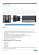
Overview Overview What is SSL UC1? UC1 is a hardware control surface that provides knob-per-function access to SSL Native Channel Strip 2 and Bus Compressor 2 plug-ins. UC1 is designed to put the fun back into mixing, with a workflow that promotes muscle-memory operation and ultimate operator confidence. The updated Channel Strip plug-in sees a graphical layout change to make it vertical, as well as a DSP refresh to include SSL’s proprietary ‘anti-cramping’ algorithms (first included in X-EQ 2).
Overview 5 Things About UC1 UC1 follows you around – like a loyal dog or trusty sidekick Opening a Channel Strip 2 or Bus Compressor 2 plug-in GUI in the DAW automatically causes UC1 to focus on that plug-in. You don’t have to look at the computer screen to use it. You can scroll through and select the Channel Strip 2 and Bus Compressor 2 plug-in you want to control and see the DAW track name that the plug-in is inserted on, directly from UC1.
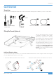
Get-Started Get-Started Unpacking The unit has been carefully packed and inside the box you will find the following items in addition to your UC1 control surface: 2 x Stands 12 volts, 5 A Power Supply and IEC Cable 1.5 m C to C USB Cable 1 x Hex Key 1.5 m C to A USB Cable 4 x Screws Fitting The Stands (Optional) UC1 has been designed to be used with or without the included screw-in stands, depending on your preference.
Get-Started UC1 Physical Specification Dimensions 11.8 x 10.5 x 2.4 ” / 300 x 266 x 61 mm (Width x Depth X Height) Weight Unboxed - 2.1 kg / 4.6 lbs Boxed - 4.5 kg / 9.9 lbs Connecting Your UC1 Hardware 1. Connect the included power supply to the DC socket on the connector panel. 2. Connect one of the included USB cables from your computer to the USB socket.
Get-Started Downloading SSL 360° & SSL Native Channel Strip 2 and Bus Compressor 2 Plug-ins UC1 requires the SSL 360° software to be installed on your computer in order to function. SSL 360° is the brains behind your UC1 control surface and it is also the place to access the 360° Plug-in Mixer. Once you have connected the UC1 hardware to your computer as described on the previous page, please download SSL 360° from the SSL website.
Get-Started Installing SSL Native Channel Strip 2 and Bus Compressor 2 Plug-ins Next, you'll need to install SSL Native Channel Strip 2 and Bus Compressor 2 plug-ins. Simply locate the downloaded Installers (.dmg for Mac, or .exe for Windows) and double-click to launch the installers. Follow the instructions.
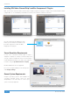
Get-Started Redeeming and Authorising Your Plug-in Licences You'll need to register your UC1 hardware in the SSL user portal to claim your SSL Native Channel Strip 2 and Bus Compressor 2 plug-in licences that are included with UC1. To register your UC1, head to www.solidstatelogic.com/get-started and follow the on-screen instructions to create an account or log into your existing one. Once logged into your account, click on REGISTER PRODUCT on the Dashboard page. Choose SSL UC1 and complete the form.
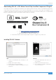
Get-Started You will need to input the serial number of your UC1. This can be found on the label on the base of your UC1 unit (it is not the number on the packaging box). For example, XX-000115-C1D45DCYQ3L4. The serial number is 20 characters long, containing a mixture of letters and digits. Once you have succesfully registered your UC1, it will appear in your Dashboard. Click Get Your Additional Software.
Get-Started Finally, open iLok License Manager, locate the UC1 Channel Strip 2 and Bus Compressor 2 licences and right-click Activate onto your computer or physical iLok.
Product Overview & Features UC1 Front Panel You can think of UC1 as two plug-in controllers in one, with the left and right hand sides dedicated to controlling Channel Strip 2 and the middle section controlling Bus Compressor 2.
Product Overview & Features Smart LED Rings Each Channel Strip 2 and Bus Compressor 2 rotary control on UC1 is accompanied by a smart LED ring, which represents the knob position in the plug-in. Channel Strip 2 plug-in controls Smart LED rings on UC1 The Virtual Notch The Channel Strip 2 GAIN controls for the EQ bands, Input and Output Trim all have an in-built 'virtual notch'.
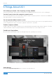
Product Overview & Features Bus Compressor Meter The most striking aspect of the UC1 front panel is the inclusion of a genuine movingcoil gain reduction meter. This shows the gain reduction activity of the selected Bus Compressor 2 plug-in. The meter is driven digitally from the plug-in and provides a helpful way of being able to keep an eye on compression activity, even with the Plug-in GUI closed.
Product Overview & Features Central Control Panel The Central Control Panel of UC1 is used to perform a number of key functions relating to the plug-ins and the Plug-in Mixer. 5 1 3 10 4 11 2 6 7 8 9 1 - 7-Segment Display Displays the position of the selected Channel Strip 2 plug-in in the Plug-in Mixer. 2 - CHANNEL Encoder Changes the selected Channel Strip 2 plug-in being controlled by UC1.
Product Overview & Features 10 - 360° Button Opens/minimises the SSL 360° software on your computer screen. 11 - Zoom Button Toggles the Zoom mode of the Plug-in Mixer. Process Order Routing You can adjust the process order routing for the selected Channel Strip 2 plug-in by pressing the ROUTING key and then turning the secondary encoder. There are 10 possible routing orders, as shown in the table below. Each routing order has a 'b' equivalent, which sources the Dynamics sidechain externally.
Product Overview & Features Connector Panel The recessed section hosts UC1's connectors. 2 1 1 - DC Connector Use the included DC Power Supply to provide power for your UC1. 2 - USB - 'C' Type Connector Connect one of the included USB cables from your computer to the USB port on UC1. This handles all of the communication between the plug-ins and UC1, via the SSL 360° software application.
Product Overview & Features Channel Strip 2 The Channel Strip 2 plug-in provides a complete SSL channel strip feature set that is based on the processing blocks of SSL's analogue consoles. It includes high and low pass filters, a four band equaliser, compressor/limiter and gate/expander.
Product Overview & Features Filter Section Channel Strip 2 has a 12 dB per octave low pass (LP) filter and 18 dB per octave high pass (HP) filter. EQ Section Beneath the filter section is the classic 4-band SSL EQ, digitally modelled on the curves of the XL 9000K EQ circuit, with fully parametric mid bands (LMF & HMF) and low and high bands (LF and HF) that default to shelving filters but can be switched to bell using the BELL button.
Product Overview & Features Dynamics Section The Dynamics section includes a Compressor/Limiter and an Expander/Gate. Both sections work independently but can be operational at the same time, providing sophisticated control of signal levels. The Dynamics section can be switched in/out using the DYNAMICS button. Compressor RATIO - determines the severity with which the signal is reduced when it exceeds the THRESHOLD. THRESHOLD - sets the point at which gain reduction is applied to the signal.
Product Overview & Features Bypass, Metering and Trims The power button at the top bypasses the Channel Strip 2 plug-in and is linked to the DAW's insert bypass feature. Input and Output metering is shown in the large segmented orange arrays, with the thinner continuous bar on the inside showing RMS (average) level over time. When clipping occurs the metering changes colour from orange to red and persists until cleared by clicking on the meter with the mouse.
Product Overview & Features Process Ordering The green area towards the bottom of the Channel Strip allows configuration of the order in which signal passes through the Channel Strip Filters, EQ and Dynamics processing blocks. Click on the double-arrows to move the position of that processing element. Please note: EQ > DYNAMICS > FILTER is not possible. This is because on SSL's analogue consoles, if the 'Filter to Input' switch is not activated, the filter will always occur directly after the EQ section.
Product Overview & Features Bus Compressor 2 The Bus Compressor 2 plug-in is based on the legendary centre section bus compressor found on SSL's large format analogue consoles. It provides high quality stereo compression for critical control over the dynamic range of audio signals. The compressor can be used for practically any application that requires superior compression.
Product Overview & Features Gain Reduction Meter The meter shows how much gain reduction is being applied by the Bus Compressor 2 plug-in in the style of the classic moving-coil meter found on SSL consoles. Oversampling Bus Compressor 2 features the ability to use oversampling DSP. Options are provided for none (OFF), 2x and 4x. When compressing material heavily (e.g.
Product Overview & Features Version Number In the bottom-right of the plug-in, the version number is shown (e.g.1.0.36). This is important to pay attention to because SSL 360° releases will sometimes require a certain version of plug-in to be installed in order for the system to function correctly. Please check the SSL 360° Release Notes article on the SSL knowledgebase to check you are running compatible versions.
Product Overview & Features SSL 360° Software Home Page SSL 360° software is not only the 'brains' behind the UC1 control surface, it is also the command centre from which new versions of software and firmware can be downloaded for your 360° compatible device. Importantly for UC1, SSL 360° hosts the Plug-in Mixer page. 1 2 3 4 5 6 7 8 The HOME screen: 1 - Menu Toolbar This toolbar allows you to navigate through the various pages of SSL 360°.
Product Overview & Features 4 - Firmware Updates Area If a firmware update becomes available for your UC1 unit, then an Update Firmware button will appear below the unit. Click on the button to start the firmware update process, being sure to not disconnect the power or USB cable(s) whilst it is in progress. 5 - Sleep Settings Clicking this will open a pop-up window, that allows you to determine the length of time before your connected 360° control surfaces go into Sleep mode.
Product Overview & Features Plug-in Mixer The Plug-in Mixer is a place to view and control the Channel Strip 2 and Bus Compressor 2 plug-ins in your DAW session. It's a bit like having access to your own virtual SSL console in your computer! Best of all, the Plug-in Mixer is available to everyone who owns Channel Strip 2 and Bus Compressor 2 and it serves as a way of enhancing your workflow.
Product Overview & Features Settings The following settings are available via the Settings option in the left-hand toolbar. Show output meters (unselected to show input meters) Allows the Channel Strip meters at the top of the Plug-in Mixer to be switched between displaying input and output levels globally. Auto select channel strips Enabling this means that moving a control on a Channel Strip 2 plug-in will cause it to be the selected channel in the Plug-in Mixer (and on UC1).
Product Overview & Features Plug-in Mixer - Zoomed Out View The Plug-in Mixer has two views that you can work with - Zoomed Out and Zoomed In View.
Product Overview & Features Zoomed Out View • Easy to navigate from one end of the Plug-in Mixer to the other. • Gives you a 'bird's eye' view of the mix. • In DAWs that allow manual re-ordering, it allows you to re-arrange your Channel Strips by clicking and dragging in the track name area. • The +/- 20 dB Output Trim parameter is placed onto a fader.
Product Overview & Features Logic Pro 10.6.1 and above - Aux Tracks Aux Tracks in Logic do not initially provide the Plug-in Mixer with a DAW track number. As a result, the Plug-in Mixer will position Aux tracks on the right-hand end of the Plug-in Mixer automatically. However, if you wish to allow Aux Tracks to dynamically update their position in the Plug-in Mixer (like with Audio and Instrument tracks), then in Logic right-click Create Track on each one.
Product Overview & Features Adding/Removing Bus Compressors to the Plug-in Mixer Plug-ins are automatically added to the Plug-in Mixer when you instantiate them in the DAW session. Deleting a plug-in in the DAW session will remove it from the Plug-in Mixer. Bus Compressor 2 Ordering in the Plug-in Mixer Bus Compressor plug-ins appear on the right-hand side of the Plug-in Mixer, as they are added to the DAW session.
Product Overview & Features Restrictions and Important Notes Multi-Mono Plug-ins in the Plug-in Mixer Installers for multi-mono Channel Strip 2 and Bus Compressor 2 plug-ins are provided as they always have been with SSL Native plug-ins. However, it is important to note the following: Logic - Multi-mono plug-ins are not supported in the Plug-in Mixer - this is because we are currently unable to retreive the DAW track name.
Troubleshooting & FAQs UC1 LCD Messages The UC1 screen will display various messages: SSL UC1 Logo This message is displayed when you power up UC1, accompanying the power up/light up sequence. 'Awaiting Connection to SSL 360° Software' This message means that UC1 is waiting for the SSL 360° software to start running on your computer. You may see this message appear when logging onto your computer, before the operating system has finished loading your user-profile and start-up items.
Troubleshooting & FAQs SSL 360° Software Messages You may encounter the following messages in SSL 360°. Here's what they mean: If the HOME page of SSL 360° is displaying the message 'NO DEVICES CONNECTED', then be sure to check that the USB cable from your computer to the USB port on UC1 has not come loose. If the HOME page of SSL 360° is displaying the message 'SOMETHING WENT WRONG... PLEASE EXIT AND RE-LAUNCH SSL 360°', then please quit SSL 360° and re-launch.
Troubleshooting & FAQs SSL Support - FAQs, Ask a Question and Compatibility Visit the Solid State Logic Help Centre to check compatibility with your system and find answers to your questions: www.solidstatelogic.com/support Thank you Don’t forget to register your UC1 for the best possible experience. www.solidstatelogic.
Safety Notices Safety Notices General Safety • Read these instructions. • Keep these instructions. • Heed all warnings. • Follow all instructions. • Do not use this apparatus near water. • Clean only with dry cloth. • Do not block any ventilation openings. Install in accordance with the manufacturer's instructions. • Do not install near any heat sources such as radiators, heat registers, stoves or other apparatus (including amplifiers) that produce heat.
Safety Notices General Safety ATTENTION! The desktop power supply must always be earthed. Refer to the User Guide for further details. CAUTION! No user-serviceable parts inside. In the event of damage to the unit or power supply contact Solid State Logic. Service or repair must be done by qualified service personnel only. CE Certification UC1 is CE compliant. Note that any cables supplied with SSL equipment may be fitted with ferrite rings at each end.
Safety Notices Instructions for disposal of WEEE by users in the European Union The symbol shown here, which is on the product or on its packaging, indicates that this product must not be disposed of with other waste. Instead, it is the user's responsibility to dispose of their waste equipment by handing it over to a designated collection point for recycling of waste electrical and electronic equipment.
www.solidstatelogic.