www.solid-state-logic.com XLogic SDI-MADI Installation and User Guide XLogic SDI-MADI This is SSL.
Important Safety and Installation Instructions This section contains definitions, warnings, and practical information to ensure a safe working environment. Please take time to read this section before installing or using this unit. Please do not dispose of these instructions. • • • • • • • • • • • • • Read these instructions Keep these instructions Heed all warnings Follow all instructions Do not use this apparatus near water Do not expose this apparatus to rain or moisture.
Contents Item Page Safety and Installation Instructions 2&3 Conformity & Warranty 4 Introduction 5 Un Pack 5 Key Features 6 Block Diagram 6 Specifications 7 Front Panel Description 8 Rear Panel Description 9 Installation 10 - 12 Setting Up and Operation 13 Synchronisation 14 Frequently asked Questions 15 Important Safety Precautions CAUTION: TO REDUCE THE RISK OF ELECTRIC SHOCK, DO NOT REMOVE COVER (OR BACK). NO USER-SERVICEABLE PARTS INSIDE.
Conformity and Warranty This document confirms that products bearing the CE label meet all the requirements in the EMC directive 2004/108/EC and LV directive 2006/95/EC laid down by the Member States Council for adjustment of legal requirements. Furthermore the products comply with the rules and regulations from 30 August 1995 referring to the electromagnetic compatibility of devices.
Introduction Congratulations on your purchase of this Solid State Logic XLogic SDI-MADI unit. Please be assured that it will provide you with many years of reliable service while delivering the pristine audio quality you expect from any Solid State Logic product. The SSL SDI-MADI is a cost-effective solution to the problem of connecting audio equipment to the SDI-based infrastructure found in many broadcast facilities today.
Key Features • 4 x SDI inputs on 75Ω BNC connection.
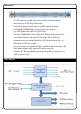
Specifications VIDEO INPUTS SYNCHRONISATION Connector/input impedance 4 x BNC sockets, 75 Ω Sample Rate Conversion SRC available on all inputs, switchable in banks of 16 Sources (External): SDI1 to 4, AES3, Video black-andburst, Wordclock Video sync input PAL/NTSC 50/60 Hz (SD) Compatible formats SDI, SD/HD/3G, compliant with SMPTE 259M, 296M, 274M, 292M, 424M or 425M VIDEO OUTPUTS Connector/output impedance 4 x BNC sockets, 75 Ω Wordclock input 48 kHz ±50ppm, DC coupled, positive going Form
Front Panel Description PSU Status Two bi-colour LEDs confirming the current status of each PSU. The LEDs are green in normal operation and flash red if a PSU fault condition is detected. SDI Lock LEDs Four tri-colour LEDs, for SDI inputs 1 to 4. Each illuminates when a valid SDI video signal is detected at its input, and the colour indicates the interface standard in use. Sync Source Selection A 3-position toggle switch for selecting the audio sync source.
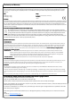
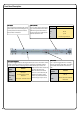
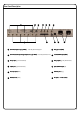
Rear Panel Description 3 1 4 2 5 6 7 8 9 10 11 12 1 SDI video inputs 1 to 4 (4 x BNCs) – internally illuminated green 7 AES3 sync out (BNC) 2 SDI video active loop through outputs 1 to 4 (4 x BNCs) - internally illuminated red 8 CoCo-axial MADI output (BNC) 3 RSRS-422 port (9-pin female Dsub) 9 AES3 outputs (37-way female Dsub) 4 GPI/O port (9-pin female Dsub) 10 Optical MADI output (ST) 5 Ext.
Installation Hardware Considerations The XLogic SDI-MADI is built in a 1U 19” enclosure. It is intended to be permanently installed in a standard 19” equipment rack. The unit has no internal fans and is cooled by natural convection. There are ventilation grilles in the top, bottom and both sides of the enclosure, and care must be taken to ensure that these are not blocked by cables or other equipment when the unit is installed.
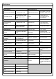
AES3 Outputs The 64 audio channels de-embedded from the four SDI inputs are available as 32 AES-3 digital audio outputs on the rear panel 37-way female Dsub connector. The outputs are 75Ω unbalanced as per AES3-4-2009, Annex D. The table below gives the pinout: Note: Each AES3 output carries 2 audio channels, thus the 16 audio channels embedded in each SDI input generate 8 AES3 outputs. To aid installation, an optional AES Signal Break Out accessory (ASBO) is available from SSL.
Installation MADI Outputs The 64 de-embedded audio channels are also available as MADI (Multichannel Audio Digital Interface), in both co-axial and optical formats. The MADI bit stream contains all 16 channels from all four SDI inputs. The channel numbering within the MADI bit stream is one-to-one, i.e., Channel 1 of SDI 1 becomes MADI Channel 1, Channel 2 of SDI 1 becomes MADI Channel 2, and so on for the remainder of SDI 1’s audio channels.
Setting Up and Operation Sample Rate Converters The sampling frequency of the audio data embedded in SDI video signals is 48 kHz. This is invariant, and is enshrined in the defining standards for all SDI formats. As with all operations involving digital audio, it will generally be desirable for the audio outputs of the SDI-MADI to be synchronised (in frequency and/or phase) with a master reference clock, which will also synchronise all other digital audio processing in the facility.
Synchronisation Sync To Wordclock SRC sync to an external wordclock is indicated by illumination of the ‘WK’ front panel LED. The clock source should be connected to the SYNC IN connector (a BNC socket) on the rear panel. Nominal frequency is 48 kHz 50ppm, and clock pulses should be of 5 V amplitude, positive-going. Sync To Video BlackBlack-AndAnd-Burst The SDI-MADI can also synchronise to a standard (SD) 1 V black-and-burst video signal.
Frequently Asked Questions Power: Power Sample Rate Converters: SDI--MADI with just one PSU (AC inlet) cable? Q: Can I run SDI Q: What are the Sample Rate Converters for? A: Yes, although it is always recommended that two AC inlet cables are connected in order to provide a level of redundancy. The two AC inlet cables should be connected to mains circuits which are as independent of each other as possible.
www.solid-state-logic.com SSL Part No. 82B4HM01A XLogic SDI-MADI This is SSL.