E Signature™ Channel Owner’s Manual
Solid State Logic ogic XL SIGNATURE CHANNEL Super-Analogue™ Outboard Owner’s Manual 82S6XL090A
XLogic E Signature™ Channel Owner’s Manual Solid State Logic Begbroke, Oxford, England, OX5 1RU • +44 (0)1865 842300 320 West 46th Street, 2nd Floor, New York, NY 10036, USA • +1 (1) 212 315 1111 Suite 401, 5757 Wilshire Blvd, Los Angeles, CA 90036, USA • +1 (1) 323 549 9090 3-55-14 Sendagaya, Shibuya-Ku, Tokyo 151-0051, Japan • +81 (0)3 5474 1144 7 bis, rue de la Victoire, le Blanc Mesnil, Paris 93150, France • +33 (0)1 48 67 84 85 Via Timavo 34, 20124 Milano, Italy • +39 (0)39 2328 094 Visit SSL at URL:
Contents 1.0 Introduction 3 2.0 Safety Considerations Safety Warnings 4 4 3.0 Installation Setting the mains voltage selector Mounting Connections 6 6 7 7 4.0 Operation Input Section Listen Mic Compressor Dynamics Section Compressor/Limiter Expander/Gate Filter Section Equaliser Section Output Section 9 9 9 10 10 11 11 12 12 5.
Solid State Logic Page 2 +20 Ø INPUT +70 MIC PAD 3RD 48V 0 +20 LINE LESS IN LCOMP MORE 230V 120V 110V KEY DYN IN LINK PRE EQ .1 +10 0 4 LIN REL RELEASE FAST ATK DYNAMICS COMPRESSOR 240V DISCONNECT POWER BEFORE REPLACING FUSES Before Connecting to the supply, see the Installation Instructions.
Introduction 1.0 Introduction The XLogic E Signature Channel unit brings the classic sound of the original early 1980s E Series console to the outboard rack of today’s artists and producers.
XLogic E Signature™ Channel Owner’s Manual 2.0 Safety considerations This section contains definitions and warnings, and practical information to ensure a safe working environment. Please take time to read this section before undertaking any installation work. 2.1 Definitions ‘Maintenance’ All maintenance must be carried out by fully trained personnel. Note: it is advisable to observe suitable ESD precautions when maintenance to any part is undertaken.
Safety Considerations Mains Supply and Phases Solid State Logic equipment is designed for connection to a single phase supply with the Neutral conductor at earth potential – category TN – and is fitted with a protective fuse in the Live conductor only. It is not designed for use with Phase (Live) and Neutral connections reversed or where the Neutral conductor is not at earth potential (TT or IT supplies).
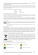
XLogic E Signature™ Channel Owner’s Manual 3.0 Installation 3.1 Voltage Selection Before connecting the mains supply ensure that the voltage range selector next to the IEC socket on the rear of the unit is correctly set. The input setting must be confirmed before applying power. The input module can be configured to be one of 4 voltage settings (one of which is invalid and should not be used – see below). The setting is indicated by a plastic pin protruding through the appropriate hole in the fuse panel.
Installation and Operation 3.2 Mounting This unit is designed to be rack-mounted. It is 1 RU (44.5mm/1.75 inch) high, its depth is: 325 mm/12.8 inches not including heatsink. 365 mm/14.3 inches including heatsink 400 mm/15.75 inches including connectors The XLogic E Signature Channel units incorporate reinforcement brackets into the chassis and so are suitable for direct rack-mounting. A 1RU space should be left above each unit to ensure adequate ventilation. 3.
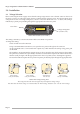
Page 8 Key In Line In Mic In 48V Ext Key Input Line Amp Line Gain PAD DYN KEY Drive Mic Amp 2 Mic Amp 1 Mic Gain LINE 4 Band Equaliser ON EQ DYN S/C Threshold LComp IN HP & LP Filters -1 FLT DYN S/C Phase Ø EQ IN FLT IP Link In/Out Line Out LINK DYN IP METER Output Gain Dynamics ADC Option Line Out IN DYN DYN PRE EQ XLogic E Signature™ Channel Owner’s Manual XLogic E Signature™ Channel Block Diagram
Installation and Operation 4.0 Operation The XLogic E Signature Channel unit is a 1U rack mounting unit containing a complete set of signal processing based upon the SL 4000 E Series channel strip – Input, Compressor/Limiter, Expander/Gate, Hi and Lo pass Filters and Equaliser. The signal processing order can be changed and the EQ and Filter sections used in the Dynamics side chain. providing a wide range of signal processing options.
XLogic E Signature™ Channel Owner’s Manual 4.3 Dynamics Section The Dynamics section of the XLogic E Signature Channel unit comprises a compressor/limiter and an expander/gate, both of which use the same gain change element. The design returns faithfully to the circuit and key components which defined the sound of the original E Series channel strip. A true RMS converter is used in the side chain whilst the gain element is an all discrete design identical to the Class A VCA chip used in the original unit.
Installation and Operation 4.5 Expander/Gate The Expander/Gate section can act either as a ∞:1 Gate or, when the EXP switch is pressed, as a 2:1 Expander. RANGE – Determines the depth of gating or expansion. When turned fully anti-clockwise, the Expander/Gate section will be inactive. When turned fully clockwise, a range of 40dB can be obtained. COMPRESSOR GATE T/HOLD T/HOLD 0 3 FAST ATK +10 6 0 10 14 20 FAST ATK -20 -30 RELEASE RATIO EXP +10 RELEASE RANGE LIN REL .1 4 1 .
XLogic E Signature™ Channel Owner’s Manual 4.7 Equaliser Section The XLogic E Signature Channel unit equaliser section defaults to the original ‘Brown Knob’ circuit that was standard on all early production E Series consoles. The two parametric mid-band sections feature SSL’s classic logarithmically symmetric design that ensures that the ±3dB up/down points retain the same musical interval from the centre frequency regardless of frequency and amplitude settings.
Installation and Operation 5.0 Signal Routing Channel Processing Order There are two switches that control the order of the signal processing elements. These are Filters to INPUT and Dynamics PRE EQ.
XLogic E Signature™ Channel Owner’s Manual Stop looking – we left this page blank… Page 14
Appendix Appendix A – Internal Links and Fuses Fuses (Mains Inlet) The mains inlet contains a single 1 amp 1.25" time delay fuse (SSL Part No. 35FJJ310). To change it disconnect the mains inlet, then using a small screwdriver prise open the mains selector cover (see illustration on page 6.). Under this cover is a removable carrier that contains the fuse – pull the carrier out to access the fuse inside. Test and replace the fuse with the same type and value if necessary.
XLogic E Signature™ Channel Owner’s Manual Appendix B – Connector Details Input Output Location: Rear Panel Location: Rear Panel Conn' Type: XLR Female Conn' Type: XLR Male Pin 1 2 3 Description Chassis Audio +ve Audio -ve Line In Pin 1 2 3 Description Chassis Audio +ve Audio -ve Key In Location: Rear Panel Location: Rear Panel Conn' Type: TRS Jack Socket Conn' Type: XLR Female Pin Tip Ring Sleeve Description Audio +ve Audio -ve Chassis Link Location: Rear Panel Conn' Type: TRS
Appendix Appendix C – Performance Specification The following pages contain audio performance specification figures for the XLogic E Signature Channel unit. No other Solid State Logic products are covered by this document and the performance of other Solid State Logic products can not be inferred from the data contained herein. Measurement Conditions For each set of figures on the following pages, the specific unit and test setup will be stated at the beginning of that section.
XLogic E Signature™ Channel Owner’s Manual Microphone Input 2 (Electronically Balanced) Measurement Conditions Signal applied to Mic Input and measured at Output. Pad switched out and Mic Gain control set to +20dB. Gain Continuously variable from +20dB to +70dB Independently switchable 22dB Pad available Input Impedance > 1.2kΩ Output Headroom > +26dBu at onset of clipping THD + Noise (-12dBu applied, +36dB gain) Adjustable between < 0.05% and 5% from 20Hz – 20kHz Frequency Response ±0.
Appendix Equaliser This is a four band equaliser that can be switched between two different sets of curves; one based on SSL’s ‘02’ (‘Brown Knob’) EQ and the other based on the latest version of the classic ‘242’ E Series (‘Black Knob’) EQ. High and low pass filters are also available. HF Band controls: Frequency Variable from 1.5kHz to 16kHz Gain Variable between ±15dB (‘02’) Variable between ±18dB (‘242’) ‘Q’ (on ‘BELL’ setting) 0.8 (‘02’) 1.
XLogic E Signature™ Channel Owner’s Manual Dynamics The unit contains a complete dynamics section, the functions of which split into two areas; a Compressor/Limiter and an Expander/Gate. Compressor/Limiter Controls: Ratio (slope) Variable from 1 to infinity (limit) Threshold Variable from +10dB to –30dB Attack Slope Normally ‘Over Easy’, switchable to ‘Hard Knee’ Attack Time Normally 30mS per 20dB*, switchable to 3mS (‘Fast Att’) Release Variable from 0.
Appendix Appendix D - Calibration Information The XLogic E Signature Channel unit is factory calibrated and should only need calibration if a potentiometer or other component has been replaced or if it is suspected that there is a problem with calibration. In all of the following instructions it is assumed that the lid has been removed and that power has been applied.
XLogic E Signature™ Channel Owner’s Manual Meter Calibration Equipment Required: Calibrated audio oscillator and audio level meter Test Signal: 1kHz sinewave @ +24dBu Input and Output: Oscillator to Line Input and Output to the audio level meter Unit Setup: 1. Set both Line Gain and Output Gain to indent (0dB). 2. Check for +24dBu output level. Adjustment: 1. Adjust VR24 until the ‘+24’ meter LED is just illuminated. 2. Reduce oscillator level to +18dBu, then +12dBu etc.
Appendix 4. Switch BLK in and re-adjust HMF Frequency for maximum level. 5. Adjust VR16 for +18dBu ±0.25dB. 6. Reset HMF Gain to its centre indent position and release the BLK switch. Recheck the audio level meter for 0dBu. HF EQ – Maximum Gain Adjustment: 1. Ensure that the BLK switch is released. 2. Set HF Gain to maximum and select HF BELL. Set the audio oscillator for 12kHz and adjust HF Frequency to find the maximum level on the audio level meter. 3. Adjust VR19 for +15dBu ±0.25dB. 4.
XLogic E Signature™ Channel Owner’s Manual Appendix E – Physical specification * Depth: 363mm / 14.3 inches 425mm / 16.75 inches casing and heatsink, excluding front panel knob(s) and rear connectors including connectors, excluding front panel knob(s) Height: 44.5mm / 1.75 inches (1 RU) Width: 444mm / 17.5 inches 481mm / 19 inches Weight: 4.0kg / 9 pounds Power: 35 Watts / 47 VA Boxed size: 520mm x 520mm x 182mm / 20.5" x 20.5" x 7.2" Boxed weight: 6.
Appendix Notes Page 25
XLogic E Signature™ Channel Owner’s Manual Page 26