Super Analogue Mic Amp Owner’s Manual
Solid State Logic SUPER ANALOGUE MIC AMP Super-Analogue™ Outboard Owner’s Manual 82S6XL020E
XLogic Mic Amp Owner’s Manual Solid State Logic Begbroke, Oxford, England, OX5 1RU • +44 (0)1865 842300 320 West 46th Street, 2nd Floor, New York, NY 10036, USA • +1 (1) 212 315 1111 Suite 401, 5757 Wilshire Blvd, Los Angeles, CA 90036, USA • +1 (1) 323 549 9090 3-55-14 Sendagaya, Shibuya-Ku, Tokyo 151-0051, Japan • +81 (0)3 5474 1144 7 bis, rue de la Victoire, le Blanc Mesnil, Paris 93150, France • +33 (0)1 48 67 84 85 Via Timavo 34, 20124 Milano, Italy • +39 (0)39 2328 094 Visit SSL at URL: http://www.
Contents 1.0 Introduction 3 2.0 Safety Considerations Safety Warnings 4 4 3.0 Installation Setting the mains voltage selector Mounting Standalone Operation Connecting to XL 9000 consoles Connecting to XLogic Remote Control unit Configuring the unit 7 7 7 7 9 11 13 4.
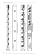
Page 2 Solid State Logic Solid State Logic HI Z -20 dB OXFORD • ENGLAND GAIN Ø -20 dB GAIN HI Z +18 +72 dB 0/LD Solid State Logic Ø MIC 1 HI Z -20 dB 48V dB MON +72 REMOTE 7/8 +18 Ø MIC 2 GAIN 100V 120V 220V 240V CHANNEL SIGNAL +18 +72 dB 0/LD Ø MIC 3 HI Z Ø -20 dB GAIN HI Z -20 dB GAIN Ø MIC 4 HI Z -20 dB GAIN +18 +72 dB 0/LD Ø MIC 5 HI Z -20 dB GAIN +18 +72 dB 0/LD Ø MIC 6 48V +18 dB CHANNEL Ø HI Z -20 dB GAIN 48V +18 dB XLogic Mic Amp (rea
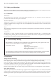
Introduction 1.0 Introduction The XLogic Mic Amp is a 1U rack mounting unit containing four ultra high quality microphone amplifiers, utilising SSL’s Super Analogue technology. The unit can be controlled either locally, from the XLogic Mic Amp Remote Control or from an XL 9000 console, allowing the mic amp to be placed close to the microphone in order to eliminate the signal degradation caused by long mic cables.
XLogic Mic Amp Owner’s Manual 2.0 Safety considerations This section contains definitions and warnings, and practical information to ensure a safe working environment. Please take time to read this section before undertaking any installation work. 2.1 Definitions ‘Maintenance’ All maintenance must be carried out by fully trained personnel. Note: it is advisable to observe suitable ESD precautions when maintenance to any part is undertaken.
Safety Considerations Mains Supply and Phases Solid State Logic equipment is designed for connection to single phase supplies with the Neutral conductor at earth potential - category TN - and is fitted with a protective fuse in the Live conductor only. It is not designed for use with Phase (Live) and Neutral connections reversed or where the Neutral conductor is not at earth potential (TT or IT supplies).
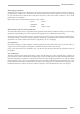
XLogic Mic Amp Owner’s Manual 100V 120V 2 3 0V 2 4 0V Mains Input Module 240 120 100 120V Setting (Use for 105-125V) 100 240 230 230 100V Setting (Use for 90-105V) 230 240 120 100 120 100 240 230V Setting (Do not use) 240V Setting (Use for 220-240V) Mains Input Programming PCB These diagrams show the PCB arrangements for the different voltage settings.
Installation 3.0 Installation 3.1 Voltage Selection Before connecting the mains supply ensure that the voltage range selector next to the IEC socket on the rear of the unit is correctly set. The input setting must be confirmed before applying power. The input module can be configured to be one of 4 voltage settings. The setting is indicated by a plastic pin protruding through the appropriate hole in the fuse panel. The setting is altered by a small vertical PCB which can be fitted in 4 positions.
Page 8 VIDEO 2 Console switched talkback output 240V 220V 120V 100V 240V 220V 120V 100V VIDEO 1 REMOTE MIC AMPS 45-48 REMOTE MIC AMPS 29-32 REMOTE MIC AMPS 13-16 M IC OUT 3 M ON IN M ON OUT Channels 1-4 M IC OUT 4 M IC OUT 3 REM 3/4 REM 3/4 REM 1/2 AUDIO/ CONTROL REM 1/2 AUDIO/ CONTROL M IC OUT 2 M IC OUT 2 M IC OUT 1 M IC OUT 1 XLR - RJ11 talkback input cable SSL Pt. No. 66C67241 M ON IN M ON OUT RJ11-RJ11 monitor bus link SSL Pt. No.
Installation 3.4 Connection to XL 9000 Consoles Remote mic amp prewiring has been fitted to many, but not all XL 9000 consoles. In many cases only a small number of channels have been wired. Check which (if any) bays of the console have been prewired for remote mic amps. Wiring can be retrofitted to any XL 9000 console if required - contact your local office or distributor for more information.
Page 10 REMOTE 7/8 240V 220V 120V 100V 240V 220V 120V 100V Console switched talkback output O X FO R D • EN G LA N D Solid State Logic REMOTE 5/6 M IC OUT 3 M ON IN M ON OUT Channels 1-4 M IC OUT 4 M IC OUT 3 REM 3/4 REM 3/4 REM 1/2 AUDIO/ CONTROL REM 1/2 AUDIO/ CONTROL M IC OUT 2 M IC OUT 2 REMOTE 1/2 M IC OUT 1 M IC OUT 1 XLR - RJ11 talkback input cable SSL Pt. No. 66C67241 M ON IN M ON OUT RJ11-RJ11 monitor bus link SSL Pt. No.
Installation 3.5 Connection to XLogic Mic Amp Remote The XLogic Mic Amp Remote (see drawing on page 2) is a 1U panel, approximately 100mm deep. Each unit will control one or two XLogic Mic Amp units (eight channels in total). It connects to each XLogic Mic Amp by two shielded RJ45 cables and is powered from the XLogic Mic Amp. Four 20 metre cables are supplied with each remote unit.
XLogic Mic Amp Owner’s Manual Table 1: Channel Display Setting - Normal Operation Channel LK5 BCD Switch Front Panel Displays Address * Position Setting Display 1 Display 2 Display 3 Display 4 0 0 0 0 0 a 0 DP DP DP DP 0 0 0 0 1 a 1 1 2 3 4 0 0 0 1 0 a 2 5 6 7 8 0 0 0 1 1 a 3 9 10 11 12 0 0 1 0 0 a 4 13 14 15 16 0 0 1 0 1 a 5 17 18 19 20 0 0 1 1 0 a 6 21 22 23 24 0 0 1 1 1 a 7 25 26 27 28 0 1 0 0 0 a 8
Configuration 3.6 Configuring the XLogic Mic Amp There are a number of internal link settings, most of which should not normally require adjustment – see Appendix A for a full listing. Those links that change the operation of the unit are described below.
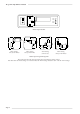
XLogic Mic Amp Owner’s Manual REM +48V PHANTOM POWER +48V PIC Controller Channel 1 MIC TRIM +18 — +78dB RST Ø DC Control from Console 25wD DC Control from remote RJ45 -1 MON 25wD -20dB Hi-Z + - REM +48V PHANTOM POWER +48V PIC Controller Channel 2 MIC TRIM +18 — +78dB RST Ø DC Control from Console 25wD DC Control from remote RJ45 -1 MON 25wD -20dB Hi-Z + - REM +48V PHANTOM POWER +48V PIC Controller Channel 3 MIC TRIM +18 — +78dB RST Ø DC Control from Console 25wD DC Contro
Operation 4.0 Operation The XLogic Mic Amp is a 1U rack mounting unit containing four ultra high quality microphone amplifiers, utilising Solid State Logic’s Super Analogue technology. The unit can be controlled locally, from the XLogic Mic Amp Remote unit or from an XL 9000 console, allowing the mic amp to be placed close the microphone in order to eliminate the signal degradation caused by long mic cables.
XLogic Mic Amp Owner’s Manual Table 2: Channel Displays (Test Mode) Channel LK5 (bit 5) BCD Switch Front Panel Displays Address * Position Setting Display 1 Display 2 Display 3 Display 4 x x x x x a 0 88 88 88 88 x x x x x a 1 seg a seg a seg a seg a x x x x x a 2 seg b seg b seg b seg b x x x x x a 3 seg c seg c seg c seg c x x x x x a 4 seg d seg d seg d seg d x x x x x a 5 seg e seg e seg e seg e x x x x x a 6 seg f seg
Appendix Appendix A – Internal links and fuses Fuses (Mains Inlet) The mains inlet contains a single 1 amp 1.25" time delay fuse (SSL Part No. 35FJJ310). To change it disconnect the mains inlet, then using a small screwdriver prise open the mains selector cover. This contains the fuse. Test and replace with the same type and value if necessary. Internal Fuses The internal power rails are also individually fused. These fuses should only be changed by suitably experienced staff.
XLogic Mic Amp Owner’s Manual Appendix B: Connector Pinouts Mic Input Channel Outputs 1 - 4 Location: Front Panel Location: Rear Panel Conn' Type: XLR Female Conn' Type: XLR Male Pin 1 2 3 Description Pin Chassis Audio +ve Audio -ve 1 2 3 Description Chassis Audio +ve Audio -ve Audio/Control Location: Rear Panel Connector Type: 25-way D-type Female Pin Description 1 14 2 15 3 16 4 17 5 18 6 19 7 20 8 21 9 22 10 23 11 24 12 25 13 ID ID ID ID ID 0V 0V Ch Ch Ch Ch Ch Ch Ch Ch 0V 0V Ch
Appendix Appendix B: Connector Pinouts (continued) Headphone Output Location: Front Panel Conn' Type: Stereo 1/4" Jack Socket Pin Tip Ring Sleeve Description Audio Left +ve Audio Right +ve 0V Monitor In / Monitor Out Location: Rear Panel Conn' Type: 6-way RJ11 Socket Pin 1 2 3 4 5 6 Description Monitor Bus -ve Monitor Bus +ve Mon Reset 0V Talkback Bus/Input -ve Talkback Bus/Input +ve Remote 1 - 2 Remote 3 - 4 Location: Rear Panel Location: Rear Panel Conn' Type: 8-way RJ45 Socket Conn'
XLogic Mic Amp Owner’s Manual Appendix B: Connector Pinouts (continued) Table 3a - XL 9000 DL to 25way ‘D’ Wiring: Channels 1-8 / 25-32 / 49-56 / 73-80 Signal Channel Channel Channel Channel Channel Channel Channel Channel Channel Channel Channel Channel Channel Channel Channel Channel Channel Channel Channel Channel ID Bit ID Bit ID Bit ID Bit ID Bit 1 1 1 2 2 2 3 3 3 4 4 4 1 1 2 2 3 3 4 4 1 2 3 4 5 Positive Negative Screen Positive Negative Screen Positive Negative Screen Positive Negative Screen Gain
Appendix Appendix B: Connector Pinouts (continued) Table 3b - XL 9000 DL to 25way ‘D’ Wiring: Channels 9-16 / 33-40 / 57-64 / 81-88 Signal Channel Channel Channel Channel Channel Channel Channel Channel Channel Channel Channel Channel Channel Channel Channel Channel Channel Channel Channel Channel ID Bit ID Bit ID Bit ID Bit ID Bit 9 9 9 10 10 10 11 11 11 12 12 12 9 9 10 10 11 11 12 12 1 2 3 4 5 Positive Negative Screen Positive Negative Screen Positive Negative Screen Positive Negative Screen Gain contr
XLogic Mic Amp Owner’s Manual Appendix B: Connector Pinouts (continued) Table 3c - XL 9000 DL to 25way ‘D’ Wiring: Channels 17-24 / 41-48 / 65-72 / 89-96 Signal Channel Channel Channel Channel Channel Channel Channel Channel Channel Channel Channel Channel Channel Channel Channel Channel Channel Channel Channel Channel ID Bit ID Bit ID Bit ID Bit ID Bit 17 17 17 18 18 18 19 19 19 20 20 20 17 17 18 18 19 19 20 20 1 2 3 4 5 Positive Negative Screen Positive Negative Screen Positive Negative Screen Positive
Appendix Appendix B: Connector Pinouts (continued) Table 4 - Channel Address Bit Linking Channel Channels Channels Channels Channels Channels Channels Channels Channels Channels Channels Channels Channels 1-4 5-8 9-16 13-16 17-20 21-24 25-28 29-32 33-36 37-40 41-44 45-48 Action connect connect connect connect connect connect connect connect connect connect connect connect pin pin pins pin pins pins pins pin pins pins pins pins 11 24 11, 24 12 11, 12 12, 24 11, 12, 24 25 11, 25 24, 25 11, 24, 25 12, 25
XLogic Mic Amp Owner’s Manual Appendix C – Performance Specification Conditions: Source impedance 150Ω unless otherwise stated. All measurements are RMS and are made using a 22Hz to 22kHz filter unless otherwise stated. General Gain: Continuously variable from +18dB to +72dB with switchable 20dB pad Input Impedance: >1200Ω switchable to 8200Ω Noise Input terminated with 150Ω Equivalent input noise: Gain EIN 70dB –129dBu 50dB –129dBu 40dB –128dBu 30dB –127.
Appendix THD + Noise In all cases THD is essentially unmeasurable, being less than the inherent noise of the amplifier until the output level exceeds +20dBu. Note: All THD+N measurements at gains above +30dB made using 40dB resistive pad to minimise effect of generator noise at low signal levels. Gain +18dB, input level +0dBu, output level +18dBu 20Hz to 10kHz THD + N < 0.0007% (20Hz - 22kHz filter) 20Hz to 20kHz THD + N < 0.
XLogic Mic Amp Owner’s Manual Appendix D – Calibration Information The XLogic Mic Amp is factory calibrated and should only need calibration if a potentiometer or other component has been replaced or if it is suspected that there is a problem with calibration. In all of the following instructions it is assumed that the top cover has been removed and that power has been applied.
Appendix Appendix E – Physical Specification * Depth: 325mm/12.8 inches not including heatsink 365mm/14.3 inches including heatsink 400mm/15.75 inches including connectors Height: 44.5mm/1.75 inches (1 RU) Width: 480mm/19 inches Weight: 4.1kg/9 pounds Power: 45 Watts/60 VA Max Boxed size: 520mm x 520mm x 182mm (20.5" x 20.5" x 7.2") Boxed weight: 6.4kg (14 pounds) * All weights and dimensions are approximate Appendix F – Environmental Specifcation Temperature Operating: Non-operating: Max.
XLogic Mic Amp Owner’s Manual Page 28