SOLEUSAIR Introduction and features Technical Service Manual for 13SEER DC INVERTER 24K Model KFHHP-22 Remarks
Specifications and technical parameters Model Function Rated Voltage Total Capacity (W) Rated Input (W) Rated Current (A) Air Flow Volume (m 3/h) (H/M/L)** Dehumidifying Volume (l/h) Indoor Unit Model of Indoor Unit Fan Motor Speed (r/min) Output of Fan Motor (w) Input of Heater (w) Fan Motor Capacitor (uF) Fan Motor RLA(A) Fan Type-Piece Diameter-Length (in) Evaporator Pipe Diameter (in) Row-Fin Gap(in) Coil lengthxheightxcoil width(in) Swing Motor Model Output of Swing Motor (W) Fuse (A) Sound Press
Model of Outdoor Unit Compressor Model Compressor Type L.R.A.
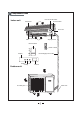
Components name cover of electrical box Indoor unit front panel manual switch front case filter air guider dispaly board manual switch remote control display heating run cooling connecting pipe and calbe receiver Outdoor unit air outlet grill drain hose
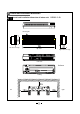
4 Overall and installation dimension Overall and installation dimension of indoor unit KFHHP-22-ID air inlet grill left tube-exit sign top view right tube-exit sign rear view Unit:mm Ceiling left right
Overall and installation dimension of outdoor unit KFHHP-22-OD unit :mm over over over bolt nutGgggg wrench
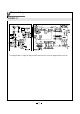
5 Electrical diagram KFHHP-22 The diagram above is subject to change without notice.
6 6.1 Function manual and operating method of controller Function manual 6.1.1 Temperature parameters ƹ Room set temperatures(Tset) ƹ Room ambient temperatures(Tin-amb) 6.1.2 Fundamental function 6.1.2.1 Cooling mode ƽtemperature setting range is 16-30¨C ƽunder this mode, fan motor of indoor unit operates at setting speed. ƽwhen compressor stops because of malfunction protection, fan motor of indoor unit still operates at setting speed. 6.1.2.
When unit is in HEAT mode, after sleep mode has been set properly, the preset Tset will be increased by 1ć after the sleep program has run for 1 hour, and Tset will be decreased by another 1ć after 2 hours.Tset has been increased by 2ć totally in two hours Then the unit will run at this temperature and at the set speed. In Auto OR fan mode, the setting temp. will not change. 6.1.3.
Controller function of outdoor unit 6.1.1 Parameters of temperature Exhausting gas temperature of outdoor unit(Tex) Ambient temperature of outdoor unit(Tam) 6.1.2 Fundermental function of system In wichever mode, once compressor start-up, it can only be close down 6 minutes later at least(not including malfunction protection/mode switch which requires compressor to stop);Once compressor closes down, it can only restart 3 minutes later at least(including mode switch, stop by remote control etc.
ƽ during heating process, when Tset ćİ(Tin-amb-3) ć İ(Tset +2)ć,the compressor operates in low frequency. during heating process, when (Tin-amb-3) ć˚(Tset +2)ć, then compressor stops running. And outdoor fan motor stops in 60s. Notice: It will take 2 minutes to power-off in 4-way valve when the unit closes down in heating mode or switch from heating mode to other modes. NJIn this mode, there is power supply for reversing valve. Range of temperature setting is 16-30ć. 6.1.2.4.
If there are 6 continuous times of protection, compressor will stop and can not restart by itself and send signal of error to indoor unit. It can only be restart by pressing “ON/OFF” button. In operation if operating time of compressor is over 7 minutes, the number of times will be zero cleared. (2) frequency demultiplying, limitation of current control If current of whole unit is high, frequency of compressor will be demultiplied or limited.
6.1.3.11 The status of indicator in outdoor unit Notice: When the unit is power-on again, the times of all the protection above (including: overloading protection, high exhausting gas temp. protection of compressor, overcurrent protection, module protection etc.) will be reset.
D14 Meaning D15 Meaning blink 6 times Unit closing down for blink 6 times frequency of current 12 A lasting for 2 minutes blink 7 times frequency limiting or demultiplying for rate of min.frequency blink 7 times Unit closing down for PFC protection blink 8 times Unit closing down for frequency variation out of control blink 8 times frequency limiting or demultiplying of compressor compressor overloading current blink 9 times frequency limiting or demultiplying for over temp.
7 Disassembly procedures Disassembly procedures for indoor unit Procedures and pictures Disassembly front panel (Refer to figure 7-1) filter electrical box top cover screw Disassemble filter Push filter inside and pull it upward.
Disassemble front case Unclench 3 screw covers;then unscrew 6 screws and lift it backward. (Refer to figure 7-4) screws Disassemble electrical box cover Unscrew the srew fixing the display board and take the board off.Hold the cover and press it to loosen the hook.
Disassemble water tray Unloose the clasp fixing water tray;lift and disassemble it (Refer to figure 7-7) water tray hook Disassemble evaporator assy Unscrew 2 screws on the clamp and remove the clamp unscew the 2 screws fixing evaporator on left and right side. Take out the evaporator by you hand and push it backward to let out the side clasps from the groove.
Disassemble motor Unscrew the screws fixing press plate and take out press plate press plate Unscrew the one M4 screws and remove the motor motor (Refer to 7-11) screws screws cross flow fan Disassemble cross flow fan fan bearing take out the bearing on the left and remove the cross flow fan (Refer to 7-12) -18-
Disassembly procedures for outdoor unit Operating procedures /pictures Disassemble front side plate front side plate unsrew the 4 srews around the front side plate and take off it (Refer to figure 7-13) srews Disassemble top cover Unsrew the srews around the top voer plate;lift the top cover and remove it (Refer to figure 7-14) srews top cover Disassemble rear grill Unscrew the 4-self tapping screws on rear side plate srews and take off the grill.
Disassemble housing case unsrew the screws around the housing case and take off it screws housing case Disassemble electrical box Screw out the 2 screws fixing the electrical box; lift it and remove it. (Refer to figure 7-17,7-18) screws Disassemble right side plate unscrew the 7 srews in right side plate,condensor side plate and valve support;lift right side plate and remove it.
Operating procedures /pictures Disassemble axial-flow fan Loosen the nut with spanner and remove it. nut axial-flow fan Disassemble motor and motor support Unscrew four tapping screws fixing the motor,and remove the motor.Unscrew the two tapping screws fixing the motor support,lift and remove it.
Operating procedures/pictures Disassemblle capillary Unsolder the joint points between capillary and other pipelines;them it can be removed capillary (Refer to figure 7-23) Disassemble valves Unsrew the two screws fixing the big valve;unsoldering the soldering points between the big valve and air-return duct;remove big valve (When unsoldering,use wet cloth to wrap the big valve completely to prevent it from being harmed by high temperature.
8 Exploded view and components&part list indoor unit KFHHP-22-ID -23-
Components and part list of indoor unit No 1 2 3 4 5 6 7 8 9 10 11 12 13 14 15 16 17 18 19 20 21 22 23 24 25 26 27 28 29 30 31 32 33 34 35 36 37 38 39 40 Part Code Description KFHHP-22-ID Wall-Mounting Frame Rear Case Water Tray Rear Grill Upper Air Deflector Lower Guide Louver Screw Cap Air Louver Swing Lever Drain Pipe Cross Flow Fan O-Gasket of Cross Fan Bearing Evaporator Assy Evaporator Left Support Front Case Sub-Assy Filter Sub-Assy Remote Control Front Panel Receiver Board Ambient Temperature S
Exploded view of outdoor unit KFHHP-22-OD -25-
Components and part list of outdoor unit No Description 1 2 3 4 5 6 7 8 9 10 11 12 13 14 15 16 17 18 19 20 21 22 23 24 25 26 27 28 29 30 31 32 33 34 35 36 37 38 39 40 41 42 43 Front Grill Housing Small Handle Clapboard Assy Axial Flow Fan Fan Motor FW60H Motor Support Sub-Assy Condenser Assy Temp Sensor Support Top Cover Rear Grill Reactor Electric Box Assy Module Support PCB JGP011 Electric Box Cover Sub-Assy Main PCB 2 W9W2 PCB Support˄up˅ PCB Support˄down˅ PCB Support Main PCB 1 W9W2 Filtering Board
9 Troubleshooting Analysis in this section is used for D.C. Variable Frequency Series. Before analysis, you can diagnose according to the code displayed on indoor unit or indicator display on outdoor unit. (Refer to Malfunction display section).
When unit is cooling or heating, both compressor and outdoor fan don't run When unit is cooling or heating, the compressor runs but outdoor fan doesn't run When cooling or heating, outdoor fan runs, but compressor doesn't run. When cooling or heating, outdoor fan runs, but compressor doesn't run.
Improper setting of temperature Adjust the set temperature Whether cooling (heating) load is proper Check the estimated load of cooling (heating) Poor cooling (heating) effect Malfunction of refrigerant flow Leakage or shortage of refrigerant Vacuumize after leakage detection and leakage repair. Charge refrigerant according to specification.
drain hose is blocked or broken replace the drain hose water leakage connector of refrigerant pipe isn't wrapped well indoor fan collides with other parts abnormal things in indoor unit abnormal shake or sound wrap and tight it again adjust the location of fan remove it compresoor shakes overly adjust the washer and tight the bolt pipes in outdoor unit collides set the pipes apart tighten the connecting bolt metal plates collides stick shake-reduction plaster between the metal plates outdoor fa
9.2 Malfunction display section Analysis or handling of some malfunction display: 1, Compressor discharge protection: Possible reasons: shortage of refrigerant; block of air filter; poor ventilation or air flow short pass in condenser; system has noncondensing gas(ge. Water, air);blockage of capillary (including filter); leakage inside 4-way valve causes incorrect operations; malfunction of compressor; malfunction of protection delay; malfunction of gas discharge sensor; too high outdoor temperature.
7. Module protection : Handling method: Check if the voltage between power module P and N is too low and if the current is too high. In normal condition, voltage between P and N should be about 320V. Abnormal Check power supply circuit of outdoor unit (if PTC resistance rectifying bridge, reactor, capacitance etc. is ok).