User's Guide
Table Of Contents
- SkyWay Wireless Bridge/Router
- Preface
- Table of Contents
- Chapter 1: Introducing Skyway
- Chapter 2: Getting to Know the SkyWay Bridge/Router
- Chapter 3: Preparing for Installation
- Chapter 4: Installing Skyway
- Chapter 5: Configuring and Managing SkyWay
- Configuring SkyWay
- Setting System Configuration Parameters
- Understanding RF-DLC
- Configuring the Ports
- Bridging
- IP Routing
- Internet Control Message Protocol
- SNMP
- Diagnostics
- File Transfer Utilities
- Security
- Chapter 6: Monitoring SkyWay
- Chapter 7: Troubleshooting Skyway
- Appendix A: Run-time Menu Tree
- Appendix B: BIOS Menu Tree Summary Table
- Appendix C: Interface Specifications and Pinouts
- Appendix D: Detailed Product Specifications
- Appendix E: Supported Protocols
- Appendix F: Error Codes
- Appendix G: SNMP Trap Messages
- Appendix H: Installation Recording Form
- Appendix I: Sources of SNMP Management Software
- Appendix J: Glossary and Basic Concepts
- Appendix K: Skyway Antennas
- Warning:
- Notes:
- 7002301: 6 dBi Omni Directional Antenna
- 7002401: 11 dBi Omni Directional Antenna
- 7002501: 16 dBi Outdoor Flat Panel Directional Antenna
- 7002601: 17 dBi Outdoor Flat Panel Directional Antenna
- 7002701: 22 dBi Outdoor High gain Flat Panel Directional Antenna
- 7002801: 8 dBi Indoor/Outdoor Patch Antenna
- 7002901: 12 dBi 110 Outdoor Sectorial Antenna
- Index

Connecting Cabling
53
Connecting to Your LAN
Connect the SkyWay to your LAN via copper or fiber optic cable.
Copper cable. The 10 Base-T/100 Base-TX (twisted pair) cable is available in 100,
200, and 300 foot lengths. This cable is terminated on the indoor side with a standard
RJ-45 connector and is intended to be connected to an Ethernet hub or switch. If a
cable length of longer than 300 feet is needed, you must order the SkyWay configured
to use a fiberoptic LAN connection. See “Fiberoptic cable” on this page for more infor-
mation.
Fiberoptic cable. Fiberoptic cable is available in longer lengths. Fiberoptic cable
transmission is not affected by the noise that can affect a copper cable, because electri-
cal transmission is converted into optical transmission. This cable is terminated on the
indoor side with a standard S/C fiberoptic connector and is intended to be connected
to a fiberoptic port on an Ethernet hub or switch.
To connect an
Ethernet cable:
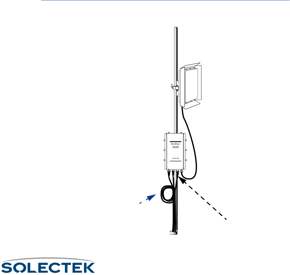
1. Connect the Ethernet cable’s 8-pin connector (10 Base-T/100 Base-TX) or 2-pin
connector (100 Base-FX) to the Ethernet port. Plug in and lock clockwise.
2. Route the cable to the console, being sure to create a drip loop.
www.solectek.com
Ethernet port
Ethernet portEthernet port
Ethernet port
(copper or fiber)
(copper or fiber)(copper or fiber)
(copper or fiber)
Drip loop and
Drip loop andDrip loop and
Drip loop and
Cable slack
Cable slackCable slack
Cable slack


