User's Guide
Table Of Contents
- SkyWay Wireless Bridge/Router
- Preface
- Table of Contents
- Chapter 1: Introducing Skyway
- Chapter 2: Getting to Know the SkyWay Bridge/Router
- Chapter 3: Preparing for Installation
- Chapter 4: Installing Skyway
- Chapter 5: Configuring and Managing SkyWay
- Configuring SkyWay
- Setting System Configuration Parameters
- Understanding RF-DLC
- Configuring the Ports
- Bridging
- IP Routing
- Internet Control Message Protocol
- SNMP
- Diagnostics
- File Transfer Utilities
- Security
- Chapter 6: Monitoring SkyWay
- Chapter 7: Troubleshooting Skyway
- Appendix A: Run-time Menu Tree
- Appendix B: BIOS Menu Tree Summary Table
- Appendix C: Interface Specifications and Pinouts
- Appendix D: Detailed Product Specifications
- Appendix E: Supported Protocols
- Appendix F: Error Codes
- Appendix G: SNMP Trap Messages
- Appendix H: Installation Recording Form
- Appendix I: Sources of SNMP Management Software
- Appendix J: Glossary and Basic Concepts
- Appendix K: Skyway Antennas
- Warning:
- Notes:
- 7002301: 6 dBi Omni Directional Antenna
- 7002401: 11 dBi Omni Directional Antenna
- 7002501: 16 dBi Outdoor Flat Panel Directional Antenna
- 7002601: 17 dBi Outdoor Flat Panel Directional Antenna
- 7002701: 22 dBi Outdoor High gain Flat Panel Directional Antenna
- 7002801: 8 dBi Indoor/Outdoor Patch Antenna
- 7002901: 12 dBi 110 Outdoor Sectorial Antenna
- Index

Component Identification
11
Component Identification
The Skyway wireless bridge/router includes the following components:
• a ruggedized, weatherproof casing
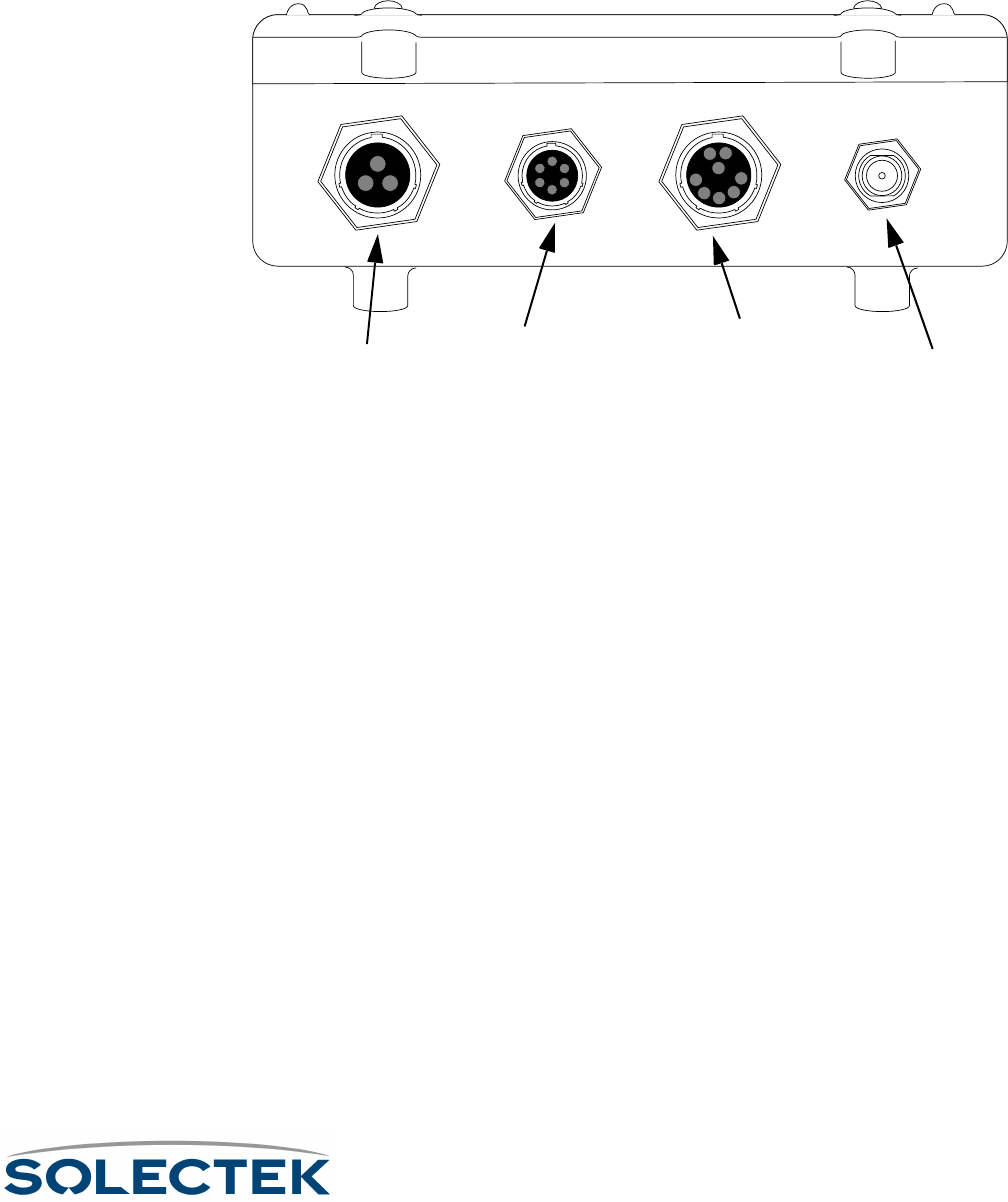
• four connectors:
Bottom View of the SkyWay Bridge/Router
Bottom View of the SkyWay Bridge/RouterBottom View of the SkyWay Bridge/Router
Bottom View of the SkyWay Bridge/Router
Power. The power receptacle (3 pin) accommodates the DC power cable supplied
with the SkyWay; it accepts 48 V DC. To apply or remove power, connect or discon-
nect the power cord to or from the AC/DC power converter.
Administration Console. The EIA/TIA-422 console connector (6 pin) accommo-
dates the console cable supplied with the SkyWay. The opposite end of the cable has a
DB-9 RS-422 connector that connects to a supplied RS-422 to RS 232 converter that
you connect to the RS-232 port of your PC or terminal. You can also connect the con-
verter to your modem. For a diagram, see “Accessing the SkyWay Bridge/Router” on
page 22.
Ethernet Port. The Data/Ethernet connector accommodates one of the following
two cables depending on the SkyWay model you ordered:
• 10/100 Base-TX (twisted pair) (8 pin)
• 100 Base-FX (fiberoptic) (2 pin)
The opposite end of either cable connects to your LAN or WAN server’s Ethernet
port.
RF. The RF connector (“N” type female) accommodates an LMR-400 RF coaxial cable
that connects to an RF antenna. For more information about antennas, see “Appendix
K: Skyway Antennas” on page 213.
For pinout information, see “Appendix C: Interface Specifications and Pinouts” on
page 181.
Power
PowerPower
Power
Administration
AdministrationAdministration
Administration
Console
ConsoleConsole
Console
Ethernet
EthernetEthernet
Ethernet
10 /100 Base-TX (shown)
10 /100 Base-TX (shown)10 /100 Base-TX (shown)
10 /100 Base-TX (shown)
or 100 Base-FX
or 100 Base-FXor 100 Base-FX
or 100 Base-FX
RF Antenna
RF Antenna RF Antenna
RF Antenna


