User's Guide
Table Of Contents
- SkyWay Wireless Bridge/Router
- Preface
- Table of Contents
- Chapter 1: Introducing Skyway
- Chapter 2: Getting to Know the SkyWay Bridge/Router
- Chapter 3: Preparing for Installation
- Chapter 4: Installing Skyway
- Chapter 5: Configuring and Managing SkyWay
- Configuring SkyWay
- Setting System Configuration Parameters
- Understanding RF-DLC
- Configuring the Ports
- Bridging
- IP Routing
- Internet Control Message Protocol
- SNMP
- Diagnostics
- File Transfer Utilities
- Security
- Chapter 6: Monitoring SkyWay
- Chapter 7: Troubleshooting Skyway
- Appendix A: Run-time Menu Tree
- Appendix B: BIOS Menu Tree Summary Table
- Appendix C: Interface Specifications and Pinouts
- Appendix D: Detailed Product Specifications
- Appendix E: Supported Protocols
- Appendix F: Error Codes
- Appendix G: SNMP Trap Messages
- Appendix H: Installation Recording Form
- Appendix I: Sources of SNMP Management Software
- Appendix J: Glossary and Basic Concepts
- Appendix K: Skyway Antennas
- Warning:
- Notes:
- 7002301: 6 dBi Omni Directional Antenna
- 7002401: 11 dBi Omni Directional Antenna
- 7002501: 16 dBi Outdoor Flat Panel Directional Antenna
- 7002601: 17 dBi Outdoor Flat Panel Directional Antenna
- 7002701: 22 dBi Outdoor High gain Flat Panel Directional Antenna
- 7002801: 8 dBi Indoor/Outdoor Patch Antenna
- 7002901: 12 dBi 110 Outdoor Sectorial Antenna
- Index

Antennas
205
align when they collide. A glancing deflection changes the angle of the wave very little,
so it remains generally in phase with the wave at the center lobe.
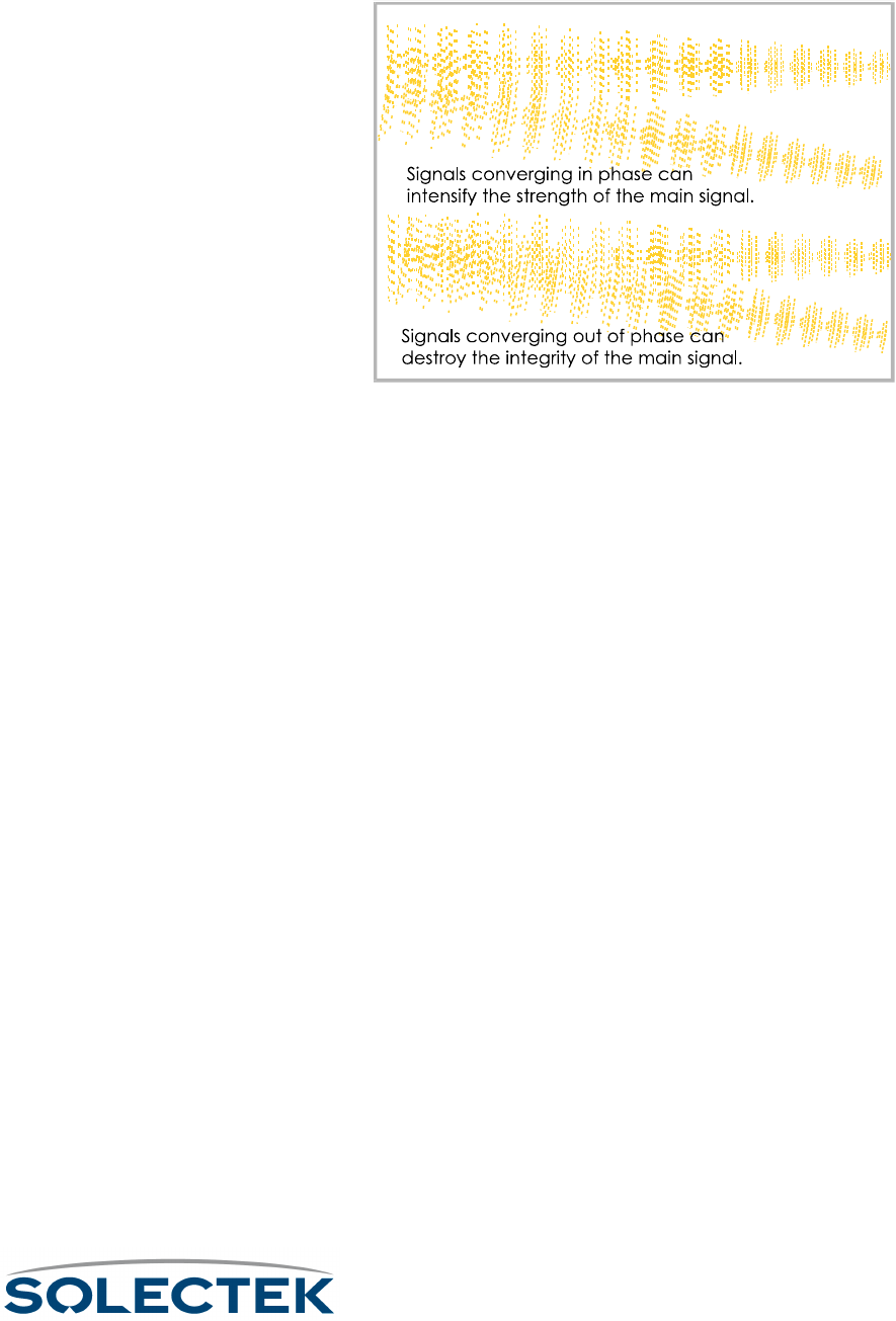
Within the signal span, there are zones where deflected signals are generally in phase
with the center lobe signal, and there are other zones where deflected signals are gen-
erally out of phase with the center lobe signal. We refer to these zones as Fresnel
(frËnl) zones.
The first Fresnel zone surrounds the center lobe where the RF signal is strongest. If
more than 40% of the first Fresnel zone is obstructed, your RF line of sight is not suffi-
ciently clear. In the first Fresnel zone and all the odd numbered Fresnel zones,
deflected signals are generally in phase with or the center lobe signal.
In the second Fresnel zone, and all even-numbered Fresnel zones, deflected signals are
up to 180× out of phase with the center lobe signal. Signals deflected from the second
Fresnel zone can cause Inter Symbol Interference (ISI) which can result in great losses
of the center lobe signal. To avoid this problem, you must place your antenna at a
height that is out of range from F2 deflections. (An antenna can be set too high as well
as too low.) Where deflection and diffraction from ground-based objects cause inter-
ference, even a small relocation of the antenna often produces a substantial improve-
ment.
Line of Sight. Radio transmission requires a clear path between antennas known as
radio line of sight. It is necessary to understand the requirements for radio line of sight
when designing a network using Solectek equipment. Radio line of sight and visual


