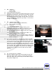
SOLBERG BBF Series Blower Base Frame Assembly Instructions Rev.: BFA-9105 These assembly instructions are to be used as a general reference guide to facilitate assembly. Please consult the blower, bushing, sheave, and drive belt manufacturer’s instruction manual for information and requirements regarding the installation of their equipment. All blower and motor models/brands are specified by the user. www.solbergmfg.
Frequently Asked Questions Important Information to Know Before You Start 1. Can I use a right hand drive blower? The Solberg BBF best accepts left hand drive blowers. To minimize issues during assembly, specify left hand drive blowers in the package design. 2. How can the BBF be adapted to work with small motor blower packages needing larger sheaves? Some smaller blower and motor packages using larger sheaves may require component elevation to allow for proper operational clearance for sheaves and belts.
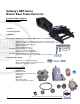
Solberg’s BBF Series Blower Base Frame Parts List Standard Solberg Supplied Base Frame Parts 1 BBF Series Base Frame 3 Channels 1 Tensioning Channel 1 Belt Guard Assorted Nuts and Bolts for assembly of a BBF Series 2” - 6” connection: (16) 1/2”-13 x 1-1/2” long carriage bolts *5/8-11 x 2” long for 6” unit (16) 1/2”-13 “whiz” nuts, (serrated flange hex nuts) *5/8-11 long for 6” unit (2) Beaded spacer tubes 7/8” long (6) 1/2”-13 hex nuts (6) 1/2” standard washers Depending on your package use either: (2) 1/2
Customer or Solberg Supplied Parts (Boot Kits available separately upon request) (1) Rubber sleeve/boot (2) Band clamps Helpful Tools: - Pipe wrench Allen wrench set 3/4" Combination wrench Screwdriver (for band clamps) Compact bolt/wire cutter Tension measuring tool Straight edge Lifting hoist 3/8” Socket wrench Soft mallet Tape measure Torque wrench (w/ sockets) Crescent wrench Solberg’s BBF Series, Blower Base Frame Assembly Instructions Relief Valve 1.1 1.2 1.3 1.4 2.1 2.
3.1 3.2 3.3 4.1 4.2 4.3 MN - (1) Blower - (1) Pipe nipple - Thread sealant Tools Needed (TN): Pipe wrench On blower, measure the distance from the bottom of the feet to the threaded inlet of the blower. Then measure the distance from the top of the inlet pipe stub to the top of the channels. This distance plus the thread engagement length of the pipe minus 1/8” inch for clearance should be the length of the pipe nipple. Seal to thread the nipple as appropriate.
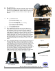
.1 6.2 MN - Skid or blocks The BBF has 30-degree cuts in the side frame. Lift the front of the BBF until these 30-degree flats rest flat on the ground. Use a skid or blocks to prop the BBF in this position. Make sure to brace the BBF on the front and rear side so that it is not able to tip either direction. Figure 6.2 7.1 7.2 7.3 7.
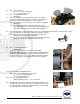
8.1 8.2 8.3 8.4 MN - (1) Electric motor - (4) 1/2”-13 x 1-1/2” carriage bolts - (4) ½”-13 “whiz” flange nuts TN - ¾” combination wrench - Lifting hoist Slide (4) carriage bolts, threaded portion up, into the channels. Using a hoist and the lifting lug, raise the motor over the BBF. As the motor is slowly lowered keep these actions in mind: 8.3.1 The channels must be slid in the slots to match the footprint of the motor. 8.3.2 The carriage bolts must be fed through the holes in the motor mounting plate.
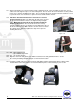
10.4 Remove only enough material to allow the drive shafts to freely pass through and accommodate any adjustments needed when tensioning the belts. Attach the belt guard to the channels. The belt guard should sit on all (4) channels. Figure 10.4 10.5 Individually place a carriage bolt, (4) total through the slot in the bottom of the belt guard and through the slot in the channel.
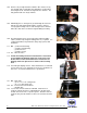
13.1 At this point begin to use the tensioning system to tighten the belts. There should be (2) hex nuts, one on either side of the angle iron piece on each carriage bolt. The hex nut on the end of the bolt is used to pull the motor on its’ channels and tighten the belts. The hex nut in between the angle iron and the channels is used to push the motor on its’ channels to square the motor and the blower sheaves. 13.2 Follow the drive belt manufacturer’s instructions to achieve proper belt tension.
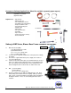
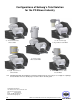
Configurations of Solberg’s Total Solution for the PD Blower Industry w/ “2G” Premium Grade Silencer Filter w/ “ST” See-Through Compact Inlet Vacuum Filter w/ “CSL” L-Style Inlet Vacuum Filter w/ “LQB” Lateral Access Silencer Filter 15.2 w/ “IVPL” Lateral Access Inlet Vacuum Filter Attaching the Filter: Depending on your blower height, it may be necessary to use a nipple or coupling to elevate the filter silencer to obtain proper clearance above the belt guard.