
User Guide
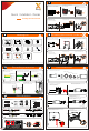

Communication connection
Make sure that the inverter is fixed on the wall.
Communication Connection(BMS/Meter/CT/COM/DRM)
Grounding Connection(manodatory)
Communication connection
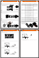
Monitoring connection
614.00697.02
Monitoring connection
Basic settings include the time, date and language.
Advanced settings can set Satety,System Switch,PVConnection, Active Power Control, Export Control, Reactive Power
Control, Grid Voltage Parameters, Grid Frequency Parameters, Grid Through Parameters, Check Parameters, Reset,
Communication Parameters and New Password.
V
PV connection
20-25 mm
12-14 mm
- Select 0.5~0.75 mm² twisted-pair and strip the 20-pin communication insulation
- Insert the insulated cord end terminal into the cable end
(ENY0512 nylon terminal for 0.5mm²/22 AWG conductor;
ENY7512 nylon terminal for 0.75 mm²/20 AWG conductor)
- Clamp with terminals press clamp
Body, Seal ring, Seal body, Claw, nut
- Disassemble the communication terminal
- Set the nut, claw, seal body, seal ring and body on the cable
- Insert the tube type terminal into the housing
according to the label
- Push the terminal-inserted housing into the body;
you will hear “Click” , if it is correctly inserted
- Please check the following table for more details about
corresponding Pin definition
Housing
- Push the seal body into seal ring, then push the claw
Clockwise tighten the nut with torque 8+/-2 N·m
- Keep the buttons on both sides pressed
and then connect it to the communication
port on the inverter. You will hear
“Click” if it is correctly connected
Inverter RS485 networking or
connectthedatacollector
Port Pin
Definition
Remark
RS-485-1
RS-485-2
DRM
1
2
3
4
5
6
7
8
9
10
11
12
13
14
15
16
RS485A IN+
RS485B IN-
GND
RS485A OUT+
RS485B OUT-
RS485A METER
RS485B METER
+5V
GND
DRM1/5
DRM2/6
DRM3/7
DRM4/8
RG/0
CL/0
GND
ConnecttheRS485 meter or
other devices
Reserved for DRM
DI
21
22
Digital IN+
Digital IN-
Inputdigitalsignal
DO
29
30
Digital OUT+
Digital OUT-
Outputdigitalsignal
SolaXcloud is a mobile phone application that can communicate with the inverter via WiFi/LAN/4G. It can realize alarm query, parameter
configuration, daily maintenance and other functions. This is a convenient maintenance platform.
Plug Dongle into “USB” port at the bottom of the inverter. After the DC side or AC side is powered on, the APP and inverter can be connected.
Please refer to the corresponding manual for details.
Router
SolaX Cloud
Router
SolaX Cloud
Ø WiFi connection
Ø LAN connection
SolaX Pocket WiFi Dongle connects to a local network within 50 m of the installation to enable access to the SolaX Cloud monitoring platform.
If WiFi isn’t suitable, the Pocket LAN enables users to connect to the network via an ethernet cable. Ethernet allows for a much more stable
connection with less interference.
Ø Basic setting and advanced setting
Ø 4G connection
SolaX Pocket 4G dongle allows you to use a 4G connection to monitor your system without the option of connecting to a local network. (This
product is not available in the UK)
Quick!
Click!