Power Unlocked by Design SAFETY, INSTALLATION, AND OPERATIONS MANUAL (United States and Canada) PowerXT®-R Module Safety, Installation, and Operations Manual © Solaria Corporation All rights reserved. Contents subject to change without notice.
Power Unlocked by Design Corporate Headquarters Contact Information 45700 Northport Loop East Fremont, CA 94538 USA solaria.com/contact Other Information Product information is subject to change without notice. All trademarks are recognized as the property of their respective owners. User documentation is updated frequently; Check the Solaria website (solaria.com) for the latest information. For warranty text refer to solaria.
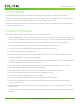
Power Unlocked by Design Table of Contents 1.0 Introduction......................................................................................................................... 4 2.0 Safety Precautions................................................................................................................ 4 3.0 Electrical Installation............................................................................................................ 5 4.0 Module Mounting..................................
Power Unlocked by Design 1.0 Introduction This document provides safety and installation information for the PowerXT® residential solar modules. Read this document before installing, wiring, or using this product. Failure to comply with these instructions will invalidate the Solaria Limited Warranty and may cause loss, damage, injury, or death. Module limited warranty is described in The Solaria Corporation PowerXT® Warranty document. This document is available at www.solaria.com. 2.
Power Unlocked by Design 2.1 FIRE RATING AND SAFETY y PowerXT R-PD & R-PM residential solar modules are UL 61730 fire type 1 rated and IEC 61730 application class II. The solar modules have been certified by an independent third-party testing laboratory. y Refer to your local authority for guidelines and requirements for building or structural fire safety. y The roof construction and installation may affect the fire safety of a building: improper installation may contribute to hazards in the event of fire.
Power Unlocked by Design y Refer to the NEC for additional multiplying factors that may be applicable. y All Solaria modules are equipped with connecting cables and locking connectors. Modules have been designed to be easily connected. The locking connectors are not to be disconnected under load. The proper procedure to disconnect the module locking connectors is as follows: Turn off the inverter(s), shut off the module DC disconnect(s) and then disconnect the locking connectors using an approved tool set.
Power Unlocked by Design tin plating on the lug. Insert a #10 flat washer between the grounding lug and the module frame. A #10 tooth lock washer must be inserted between the nut and the module frame to break the anodized layer of the frame. This mechanical bond between the tooth lock washer and the frame of the module will ensure a good electrical bonding path. The #10-32 assembly attachment screw must be tightened between 20-25 inch-pound.
Power Unlocked by Design come into contact with the module. y Ensure that the modules are not subject to wind or snow loads in excess of the maximum permissible loads and are not subject to excessive forces due to thermal expansion of the support structure. y Modules have been tested to Mechanical Loading Test requirements of IEC/UL 61730. y The fire rating of this module is valid only when mounted in the manner specified in the mechanical mounting instructions.
Power Unlocked by Design PowerXT xxxR-PD y Mounting Using Clamps: When using clamps, place clamps within the “CLAMP AREA A” or “CLAMP AREA B” as indicated on the diagram below. Follow clamp manufacturer’s recommended hardware and torque requirements for solar installations. Various clamp systems specifically designed for PV module mountings are available and compatible with PowerXT. In the absence of manufacturer’s recommendations for clamp size, Solaria recommends minimum clamp size of 40mm (1.57”).
Power Unlocked by Design PowerXT xxxR-PM y Mounting Using Clamps: When using clamps, place clamps within the “CLAMP AREA A” or “CLAMP AREA B” as indicated on the diagram below. Follow clamp manufacturer’s recommended hardware and torque requirements for solar installations. Various clamp systems specifically designed for PV module mountings are available and compatible with PowerXT. In the absence of manufacturer’s recommendations for clamp size, Solaria recommends minimum clamp size of 40mm (1.57”).
Power Unlocked by Design y Mounting Using Rail-less Racking Systems: Typical rail-less racking system layout is shown in the diagram below. Attachments are to be made on the long side of the module with maximum attachment span of 48 inches and maximum cantilever of 17 inches. Follow racking system manufacturer’s recommendations for coupling clamps at the module corners, torques, and bonding methods. For rail-less systems, maximum allowed loading is 2400Pa (front) and 2400Pa (rear). 4.
Power Unlocked by Design 5.0 Maintenance Solaria modules are virtually maintenance free. Following simple maintenance steps will ensure reliable production of DC electric power for the expected life of the product. y Inspect electrical and mechanical connections for safety and corrosion once every year. y Under most weather conditions, normal rainfall is sufficient to keep the module glass surface clean.
Power Unlocked by Design 8.0 Mechanical Dimensions PowerXT®-xxxR-PX PowerXT®-xxxR-BX y Nominal dimensions in millimeters and [inches] – Not Drawn to Scale y 4x 4.5mm [0.18in] Grounding Holes ‘A’ y 4x 7.0mm [0.28in] x 10.0mm [0.39in] Mounting Slots ‘B’ y Module Weight: 20 kg (44 lbs.) 13 Safety, Installation, and Operations Manual © Solaria Corporation All rights reserved. Contents subject to change without notice.
Power Unlocked by Design PowerXT®-xxxR-PD PowerXT®-xxxR-BD y Nominal dimensions in millimeters and [inches] – Not Drawn to Scale y 4x 4.5mm [0.18in] Grounding Holes ‘A’ y 4x 7.0mm [0.28in] x 10.0mm [0.39in] Mounting Slots ‘B’ y Module Weight: 21 kg (46 lbs.) 14 Safety, Installation, and Operations Manual © Solaria Corporation All rights reserved. Contents subject to change without notice.
Power Unlocked by Design PowerXT®-xxxR-PM 8 7 6 4 5 2 3 1 NOTES: THE TOLERANCES AND DIMENSIONS ON THIS PAGE ARE FOR THE REFERENCE OF THE INSTALLER FOR MANUFACTURING INFORMATION REFER TO MANUFACTURING DRAWINGS F F 64.72in 1644mm .98in 25mm 5.83in 148mm 5.83in 148mm A B B A E E .43in 11mm D D 47.40in 1204mm .07in 1.70mm 4 5 1.57in 40mm 2 3 1 NEGATIVE (-) 1000mm (3.3 ft) 1.38in 35mm POSITIVE (+) 1000mm (3.3 ft) C C F 5.83in 148mm A B A D B XT-A018 02 REV 64.
Power Unlocked by Design Solaria USA 45700 Northport Loop East Fremont, CA 94538 United States of America T: +1-510-270-2507 www.solaria.com 16 Safety, Installation, and Operations Manual © Solaria Corporation All rights reserved. Contents subject to change without notice.