
Installation Guide


5. If you replace a Connection Unit with a built-in Energy Meter, disconnect the RS485
connector from the inverter communication board.
6.
Unscrew the two conduit nuts in the Primary Unit securing the Connection Unit to
it, see
Figure 50
.
7. Open the Connection Unit cover and disconnect the DC, AC and communication
wires. Unscrew the two conduit nuts securing the Connection Unit to the external
conduits.
8. Release the Connection Unit bracket from the wall.
9. Carefully remove the Connection Unit with its mounting bracket from the wall.
Installing a New Connection Unit
1. Position the new Connection Unit below the inverter and from the inside of the
Primary Unit grab the AC and DC wires extending from the switch conduits.
2. Securely screw the two conduit nuts onto the conduit ends in the inverter.
3. Attach the Connection Unit with its bracket to the wall and tighten its screw.
Connecting the Connection Unit to the Primary Unit
1. Connect the DC, as follows, see
Figure 49
:
Connect the red wire to any of the DC+ terminals in the inverter.
Connect the black wire to any of the DC- terminals in the inverter.
2. Connect the communication wire to the communication board.
3.
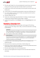
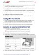
Connect the AC wires according to the labels on the ACterminal blocks, as follows:
Three Phase Inverter
Wire type Connect to terminal
Figure 51: Primary Unit AC terminals
Line 1 L1
Line 2 L2
Line 3 L3
PE (grounding)
Neutral N
4. Tighten the screws of each terminal with a torque of 0.88-1.1 lb.*ft / 1.2-1.5 N*m.
Appendix D: Replacing System Components 97
Three Phase Inverter with Synergy Technology Installation MAN-01-00401-1.5